
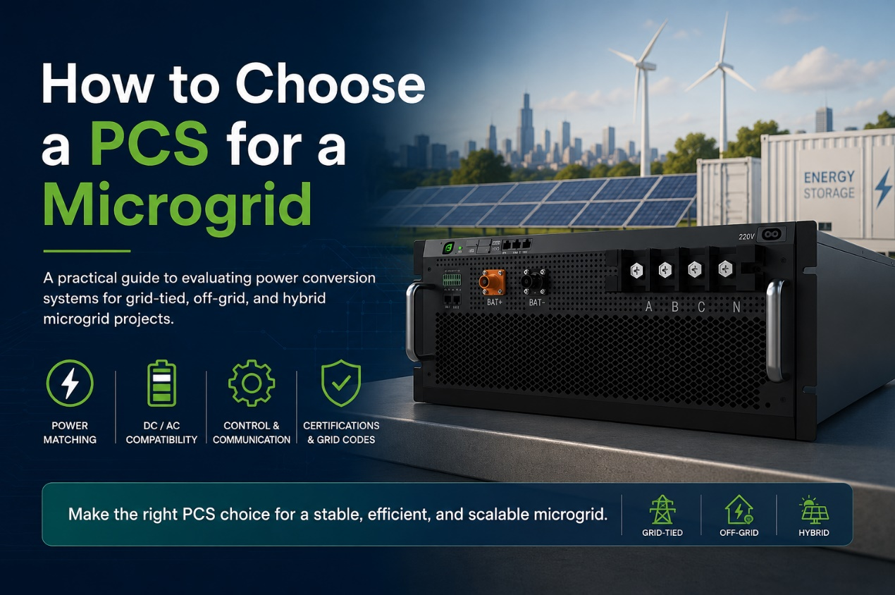
Choosing the right power conversion system (PCS) is critical to the stability, efficiency, and scalability of a microgrid. Whether the project is grid-tied, fully off-grid, or built around solar, battery storage, and diesel generation, the PCS must match the system’s voltage, power, control, and communication requirements. This guide explains how to evaluate PCS options and select the best fit for different microgrid applications.
Understanding PCS Requirements for Microgrid Projects
Project Goals and Expected Outcomes
Before you compare a single PCS, define what your microgrid needs to achieve. Your goal should drive the selection from the start — see which one matches your project:
- Reduce diesel consumption: requires a PCS that can manage battery dispatch against a generator and shift load intelligently between sources.
- Provide backup power: requires fast transfer capability and reliable islanding when the grid drops.
- Replace grid dependence entirely: requires grid-forming control, since there is no utility grid to synchronize to.
- Integrate renewable generation: requires a PCS that can absorb variable solar or wind output without destabilizing the system.
Who This Microgrid PCS Selection Guide Is For
This guide is written for project engineers, EPC contractors, and system integrators specifying a PCS for commercial, industrial, or remote microgrid projects. It applies equally to new-build systems and to retrofits adding storage to an existing solar or diesel installation.
Microgrid PCS Selection Preparation: Required Data, Tools, and Resources
You cannot compare PCS options meaningfully without a defined dataset. Collecting this information before contacting vendors saves time and avoids selecting hardware that has to be replaced later.
Essential Information for Microgrid PCS Selection
- Site electrical single-line diagram
- Load profile (peak/average demand, load type: resistive, inductive, motor-driven)
- Battery/energy storage specifications (chemistry, voltage range, capacity)
- Renewable generation source data (PV, wind capacity and variability)
- Grid connection status (grid-tied, off-grid, or hybrid)
Tools and Resources for Evaluating Microgrid PCS Optionsl
- PCS/inverter datasheets from candidate vendors
- Local grid interconnection standards
- System sizing/simulation software
- Cost and lifecycle (O&M) estimation spreadsheet
A few points across this list are worth flagging before you move on:
- Load profile: motor-driven loads draw a startup surge well above their running current. Size the PCS for that surge, or it will trip during normal operation.
- Battery specifications: the PCS DC input window has to cover the battery’s full voltage range, from low state of charge to fully charged, not just its nominal voltage. Get this wrong, and you either clip usable battery capacity or push the battery outside its designed range.
- Cost and lifecycle spreadsheet: go beyond the purchase price. A unit with a lower sticker price but lower efficiency or a shorter design life often costs more over twenty years than a higher-priced alternative.
How to Select a PCS for a Microgrid: Key Evaluation Steps
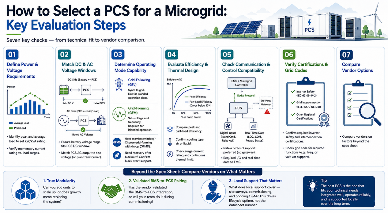
With the project data collected, evaluating candidate PCS units comes down to seven checks — from power and voltage matching through to vendor comparison.
Step 1 — Define System Power and Voltage Requirements
Identify peak and average load to set the required kW/kVA rating, then check the momentary current rating against your load profile’s surge data.
Step 2 — Match DC and AC Voltage Windows
Check that the battery’s full operating voltage range sits entirely inside the PCS’s DC window. On the AC side, match the PCS’s rated output to the site voltage before comparing price — a mismatch means adding an external transformer, so factor that cost in early.
Step 3 — Determine Operating Mode Capability
Grid-following (GFL) control syncs to an existing grid and cannot run an islanded microgrid alone. Grid-forming (GFM) control sets voltage and frequency itself, which off-grid operation requires. If the project must switch between grid-tied and islanded modes without an outage, look for grid-forming with droop (GFMD); if it must recover after a full blackout, confirm the PCS supports black start.
Step 4 — Evaluate Efficiency and Thermal Design
Compare peak efficiency, but check part-load efficiency too, since it drops sharply below 10% of rated power. Confirm whether cooling is air- or liquid-based, and ask for both the surge-current rating and the continuous thermal limit, since these are two different numbers and vendors sometimes quote only the more favorable one.
Step 5 — Check Communication & Control Compatibility
Confirm the PCS natively supports your EMS or microgrid controller’s protocol — a third-party gateway adds a point of failure, so native support is the safer choice. It should also have dedicated digital inputs for the island command and relay acknowledgment signals, and report state of charge, state of health, and power conversion status back to the EMS in real time.
Step 6 — Verify Certifications and Grid Codes
Certifications determine whether a utility will approve the interconnection at all, so confirm the PCS holds the relevant inverter safety and interconnection certifications for your market. Also check the region’s grid code for any additional required functions, such as frequency or volt-var compensation.
Common certifications and grid codes by region:
| Region | Certification / Grid Code |
| United States | UL 1741, IEEE 1547 |
| European Union | EN 50549, VDE-AR-N 4105 (Germany) |
| United Kingdom | G99 |
| Australia / New Zealand | AS/NZS 4777.1, AS/NZS 4777.2 |
| Japan | JIS C 8961, JET certification |
Step 7 — Compare Vendor Options
Once technical requirements are set, compare vendors on three things beyond the spec sheet, since most established vendors already meet baseline certifications.
First, check whether the platform is genuinely modular — can you add units to scale up, or does growth mean replacing the system? Second, ask whether the BMS-to-PCS pairing has been validated by the vendor, or whether that integration work falls on your team during commissioning. Third, confirm what local support actually covers — site surveys, commissioning, and ongoing O&M — since this is what determines how much downtime the project absorbs over its lifecycle, not the number on the datasheet.
Choosing a PCS for Different Off-Grid and Hybrid Microgrid Applications
The seven steps above cover the general case. Two applications carry extra requirements worth flagging separately: island microgrids running on solar and storage alone, and remote industrial sites blending solar, diesel, and battery.
Remote-Island Solar-Plus-Storage Microgrid
Key points to watch:
- Grid-forming (GFM) control with black start capability
- Wide DC input window to absorb fast PV swings
With no utility grid to sync to, GFM control and black start are not optional — they’re the baseline for this application. Cloud cover can swing PV output within seconds, so the DC input window needs enough margin to absorb that swing without pushing the battery outside its designed range.
Remote Mining Solar-Diesel-Battery Hybrid Microgrid
Key points to watch:
- Battery dispatch coordinated against the diesel generator
- Momentary current rating sized for motor startup surge
- Continuous thermal limit, not just peak efficiency
Diesel stays in the mix as backup capacity, so poor coordination during start/stop events can destabilize the system. Motor-driven loads like crushers and conveyors also draw a startup surge well above running current, tripping an undersized PCS.
High-ambient temperatures with limited maintenance access mean peak efficiency alone isn’t enough — the continuous thermal limit is what determines real-world performance.
One Platform, Every Scenario: Enjoypowers 105/125kW PCS
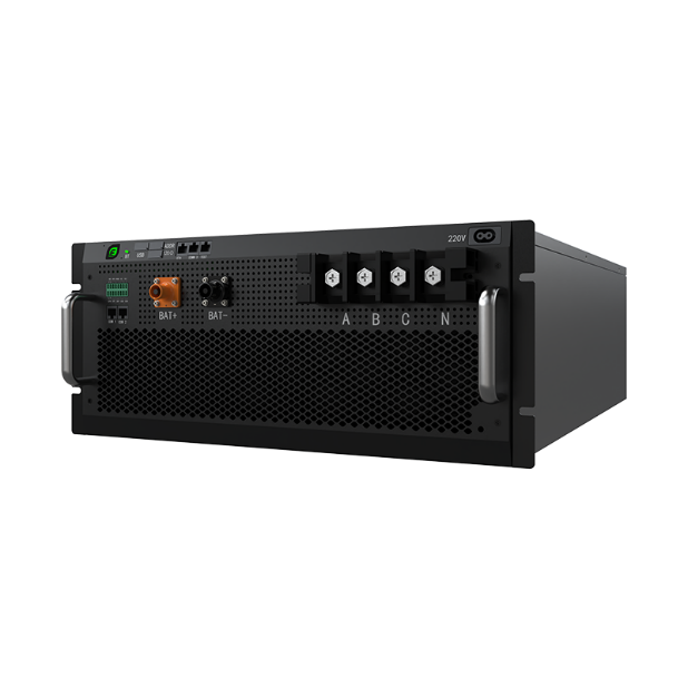
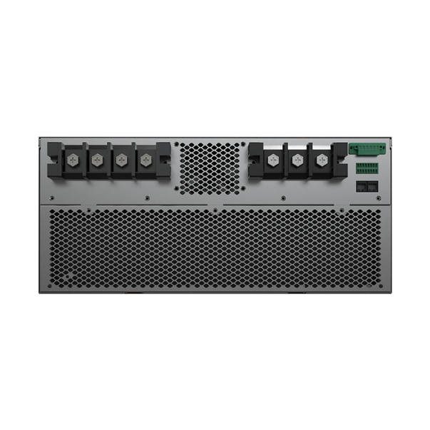
A clean datasheet doesn’t always survive real microgrid conditions — unstable diesel switching, blackout recovery, harsh ambient environments. Enjoypowers built its 105/125kW PCS around that gap, with a set of advantages worth flagging directly.
- Grid-forming (VSG) control: establishes voltage and frequency from the battery side, with black start and seamless on/off-grid transfer in under 20ms.
- Independent phase control: supports 100% unbalanced loads at full rated power, avoiding the derate that symmetric PCS units face under zero-export rules.
- Harsh grid tolerance: virtual impedance and adaptive damping keep output THDi under 3% even against grid THDu up to 30%.
- Industrial-grade reliability: full-board conformal potting against dust, salt spray, and humidity, an IP66 enclosure with C5 anti-corrosion coating, and 50°C ambient operation with zero derating — backed by over ten billion cumulative hours of field-validated firmware.
Whether the project is an island microgrid, a diesel-hybrid site, or a straightforward grid-tied commercial installation, this level of grid-forming control and environmental tolerance holds up across the conditions.
Get Started with Enjoypowers 105/125kW PCS
Choosing the right PCS comes down to matching voltage, control mode, and communication requirements to your project’s specific conditions — not just comparing rated power. The Enjoypowers 105/125kW PCS is built around three core modules that combine into standard configurations for different project scales:
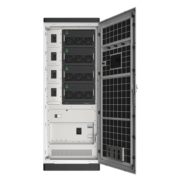
- Pure 500kW BESS PCS cabinet: 4×125kW PCS modules in parallel, for peak shaving, capacity expansion, and VPP participation
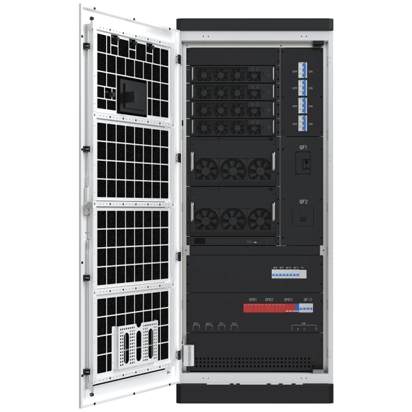
- All-in-one microgrid hybrid cabinet: PCS, DCDC, and STS in one footprint, for minimum floor space and field wiring
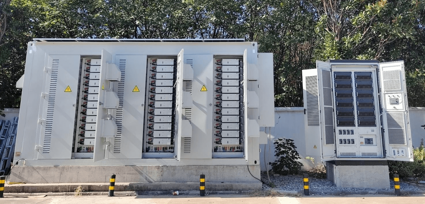
- MW-scale container deployment: up to 12 PCS modules per container, coordinating via VSG without site-level control wiring
Contact us for a project consultation, or download the datasheet to review full specifications.
FAQs
Q1: Is a PCS the same thing as a solar inverter?
Not quite. A standard grid-tied solar inverter only pushes power one direction and needs an existing grid to sync to, while a battery PCS is bidirectional, and a grid-forming PCS can charge and discharge the battery while establishing voltage and frequency on its own. The Enjoypowers 105/125 kW PCS is a good example: built with VSG control, it can run a system with no external grid at all. If your setup includes battery storage or needs to operate off-grid, you need a PCS like this, not just an inverter.
Q2: How do I size a PCS if I expect my microgrid to grow later?
Size for near-term peak load, but pick an architecture that scales modularly so you can add units as demand grows instead of replacing the whole system. Paralleling limits matter more than people expect here — the Enjoypowers 105/125 kW PCS supports up to 12 units paralleled together without communication wiring between them, so a project can start small and expand later without re-engineering the control network.
Q3: Can I mix PCS units from different vendors in the same microgrid?
Technically, sometimes, but it is rarely a good idea. Differences in control algorithms and communication protocols can cause units to fight each other during load transients or black starts, especially off-grid. It is usually better to standardize on one proven platform — the Enjoypowers 105/125 kW PCS, for instance, provides a consistent control platform, helping units behave predictably as a project scales.