
Data Center Power Quality
Power quality engineered for racks that don't tolerate problems.
Active harmonic filtering and reactive power compensation for data centers, colocation facilities, and edge-of-network IT infrastructure. Designed for the 5 ms-tolerance world of modern server PSUs and PDU equipment.
response time
5 ms
target attainable
THDi < 5%
supported
N+1 redundancy
Why data centers need PQ
Four ways data center power quality issues become real problems.
Modern server PSUs are sensitive. Modern UPS systems are sensitive. The infrastructure they sit on can’t have power quality problems — the cumulative effect on uptime, equipment life, and cooling load is significant.
Server PSUs generate harmonics at scale.
Each modern server PSU draws non-linear current with significant 3rd, 5th, and 7th harmonics. Aggregate across 1000+ servers per data hall and the harmonic load on transformers and UPS systems becomes substantial. Active filtering at the PDU or main bus removes the cumulative distortion.
Voltage events ride through UPS — or don't.
Modern double-conversion UPS systems isolate IT loads from most voltage events. But voltage transients pass through partially, and frequent events stress the UPS rectifiers. Pre-UPS active conditioning keeps the upstream supply clean, reducing UPS stress and extending UPS battery life.
Utility PF penalties scale with facility size.
Large data centers see 5-20 MW of utility-side load. Even small PF deviations from 1.0 mean substantial penalty charges on industrial tariffs. Maintaining PF at 0.99+ across the facility eliminates a meaningful OpEx line item.
Cooling load tracks harmonic distortion.
Harmonics cause transformer heating, cable heating, and equipment temperature rise. In data centers, where every kW of equipment heat must be removed by cooling, harmonic-induced heat directly increases cooling cost. Cleaner power means lower PUE.
Solution architecture
Two installation points, depending on facility tier.
Data center PQ installations target two common points:
Point A · PDU level (per data hall or rack row)
AHF + SVG (Active Harmonic Filter + Static Var Generator)
AHF/SVG installed at the PDU panel, filtering the harmonics from one data hall or rack row. Best for: phased deployment, mixed-tenant colocation, isolating PQ to specific high-density zones.
Point B · Facility-level (utility intake or main bus)
SVG + Thyristor-Switched Capacitors
Larger AHF/SVG installation at the utility intake, filtering aggregated harmonics from the entire facility. Best for: hyperscaler builds, dedicated single-tenant data centers, facilities with consistent load profile across data halls.
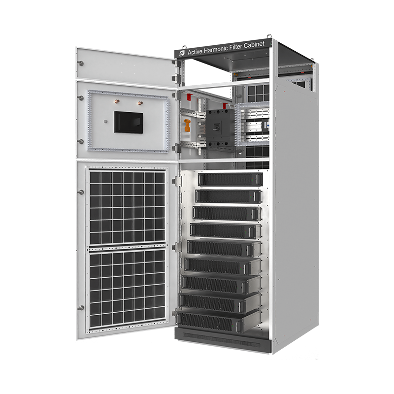
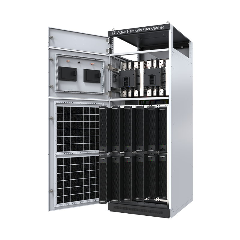
For Tier III / Tier IV facilities, N+1 redundancy is supported: AHF/SVG can be deployed with redundant modules where the failure of any one unit doesn’t impact filtering performance. The cabinet-integrated configurations naturally support this — a SinL Pro Cabinet with 12 modules can operate with 11 active and 1 redundant.
Recommended configurations
Three sized configurations covering 90% of Data center installations.
For specific harmonic surveys and bill-of-materials sizing, send 1 week of 15-minute interval data and a representative harmonic spectrum at the PCC.
Configuration A · Edge data center
small colocation (50-200 kVA)
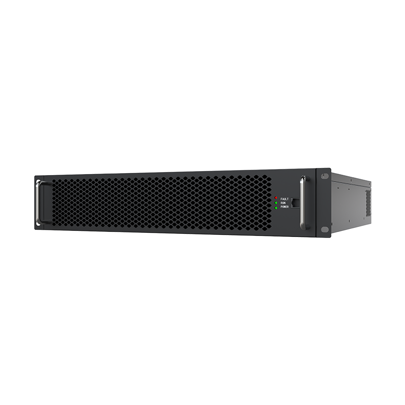
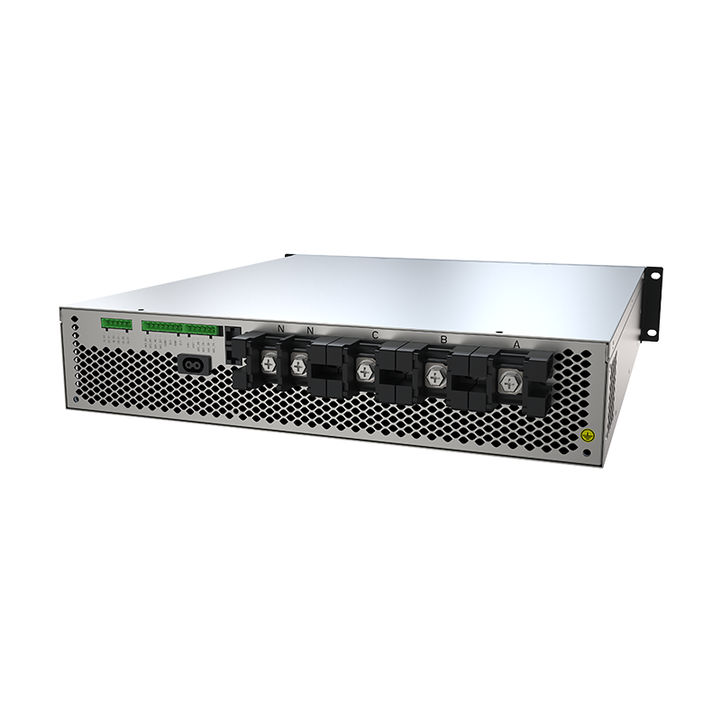
- AHF: 1-2 × SinL Pro 50-100A modules (Plug-in form factor for rack mounting near PDU)
- SVG (if needed): SinL Pro 25-50 kVar modules
- Voltage: 400 V (most common)
- Typical use: Edge data center, small enterprise data hall, regional colocation
Configuration B · Mid-size data center★
200 kVA - 2 MVA per data hall
- AHF: 4-8 × SinL Pro 150A or SinE 200A modules in Cabinet
- SVG: Configured per facility reactive profile
- Voltage: 400 V or 690 V (depending on transformer design)
- Typical use: Tier II/III colocation, single-tenant data center
Configuration C · Hyperscale facility
2 MVA+ per data hall
- AHF/SVG: Multiple SinL Pro Cabinets in N+1 configuration
- Installation point: Both per-hall PDU and facility-level depending on architecture
- Voltage: Usually 690 V or higher at the main bus
- Typical use: Hyperscale data center, large cloud provider facility
Engineer FAQ
Questions our application engineers get most often.
Almost always upstream of UPS (between utility and UPS input). This keeps the supply clean for the UPS rectifier, reducing UPS stress and extending battery life. For double-conversion UPS, the UPS itself isolates downstream IT loads from most events — the AHF/SVG’s job is keeping the supply side clean. Installing AHF/SVG downstream of UPS is rare and only done in specific edge cases.
Modern UPS double-conversion rectifiers are themselves harmonic loads (typical 5-15% THDi at the UPS input). Active filtering upstream cancels both the UPS-induced harmonics and the building’s other harmonic loads — resulting in clean current at the utility meter regardless of UPS load patterns.
Cabinet configurations support N+1 natively. A SinL Pro Cabinet with 12 modules can operate at full rated capacity with any 11 modules active — the 12th provides redundancy. Module failure is detected and the remaining modules automatically redistribute load. Module hot-swap during operation is supported with proper procedure.
AHF/SVG units provide Modbus TCP, BACnet, and SNMP communication interfaces. Integration with major DCIM platforms (Schneider EcoStruxure, Vertiv Trellis, Sunbird) is straightforward. Key metrics exposed: real-time PF, THDi, kVAR injected, module status, fault counters. We provide integration documentation with the commissioning package.
Cabinet-integrated systems have built-in forced-air cooling — they self-manage their own thermal load. The cabinet does emit heat (the filter does dissipate the harmonics into heat), so the switchroom needs to be sized for this. Typical heat rejection: 2-3% of the filter’s rated capacity. For a 1 MVA AHF, that’s roughly 20-30 kW of switchroom cooling load.
Active filtering meets current and proposed PQ standards across major markets (China GB/T, IEC, IEEE, EN). Standards are tightening over time — particularly around THDi limits for medium- and high-power facilities. Active filtering is “future-compliant” by design: as standards tighten, the same hardware adjusts to new targets via firmware update; passive filtering would require hardware re-engineering.