
Energy storage built for critical-load continuity.
A dual-PCS architecture that separates grid-side charging from critical-load power supply. The battery and off-grid PCS maintain the critical AC bus through utility outages, charging-side PCS faults and generator transitions.
Not a conventional UPS. System performance, redundancy, transfer requirements and compliance are defined according to the project.
Continuity changes the architecture.
Peak shaving asks how much energy can be shifted. Critical-load backup asks a different question: what continues operating while the grid, a charging PCS or the generator is unavailable?
01
A system optimized for tariff arbitrage may not provide an independent critical-load power path when utility power disappears.
02
The UPS-like architecture separates grid-side charging from the off-grid PCS responsible for maintaining the critical AC bus.
03
The battery supports critical loads while the diesel generator starts, establishes voltage and synchronizes before the ATS admits the source.
See how the system behaves — not just how it is connected.
Use the operating-state buttons to explain normal charging, a single charging-side PCS fault, utility outage, generator synchronization and return to utility.
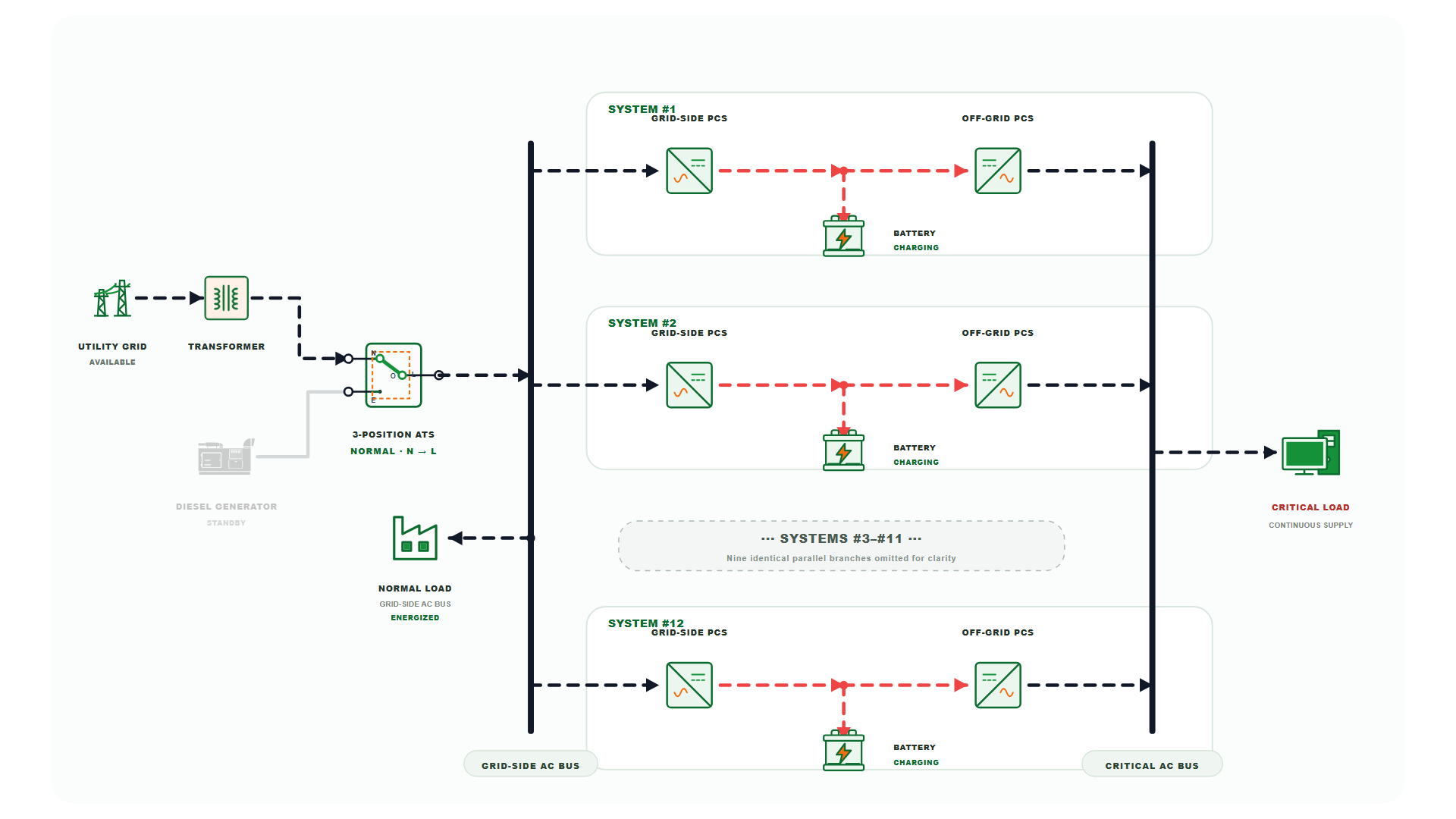
Grid → Transformer → ATS(N) → grid-side PCS charges the batteries. Off-grid PCS continuously maintains the critical-load AC bus.
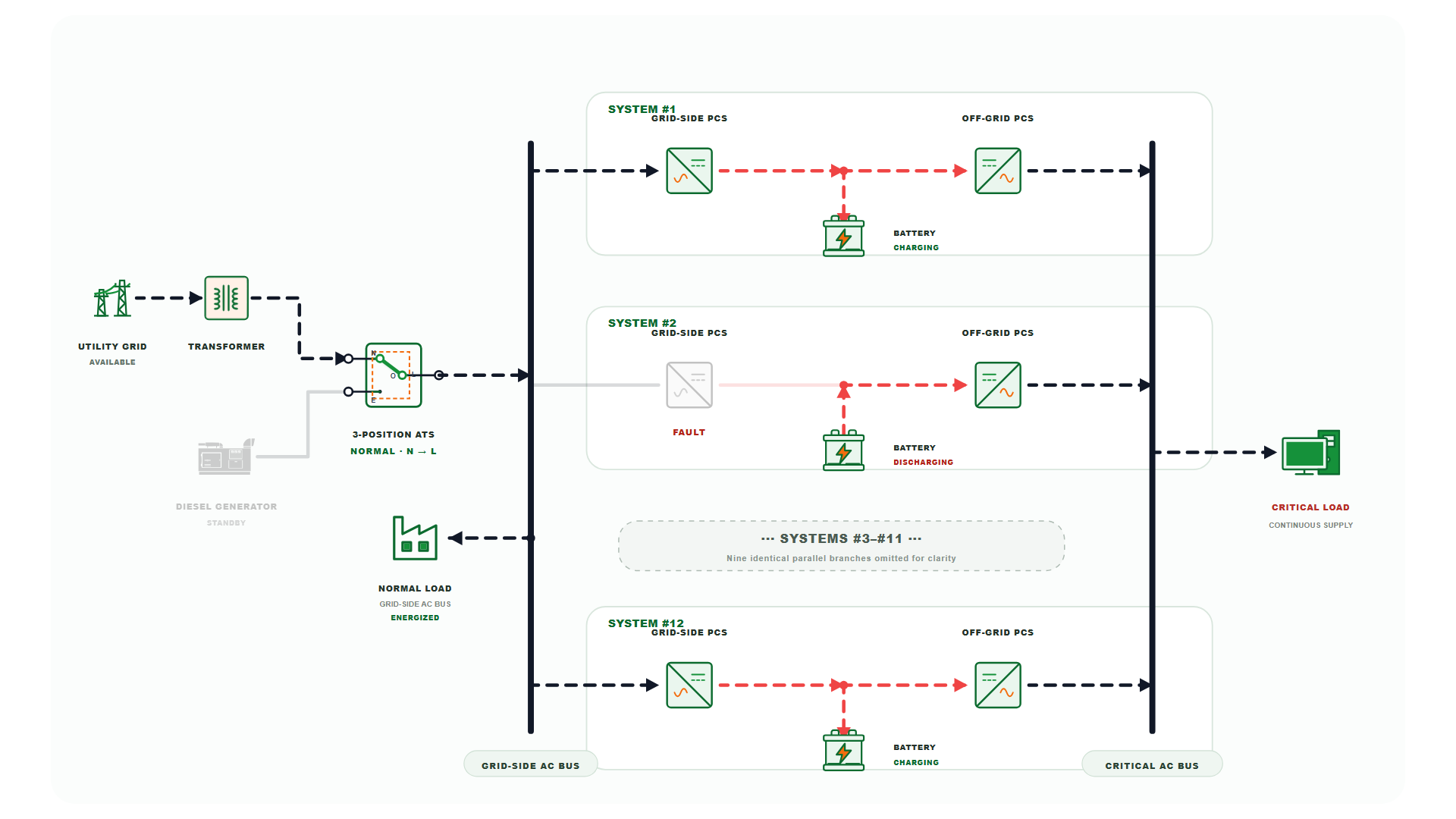
One grid-side PCS is isolated. Its battery discharges to its off-grid PCS while the remaining charging PCS continue normal operation.
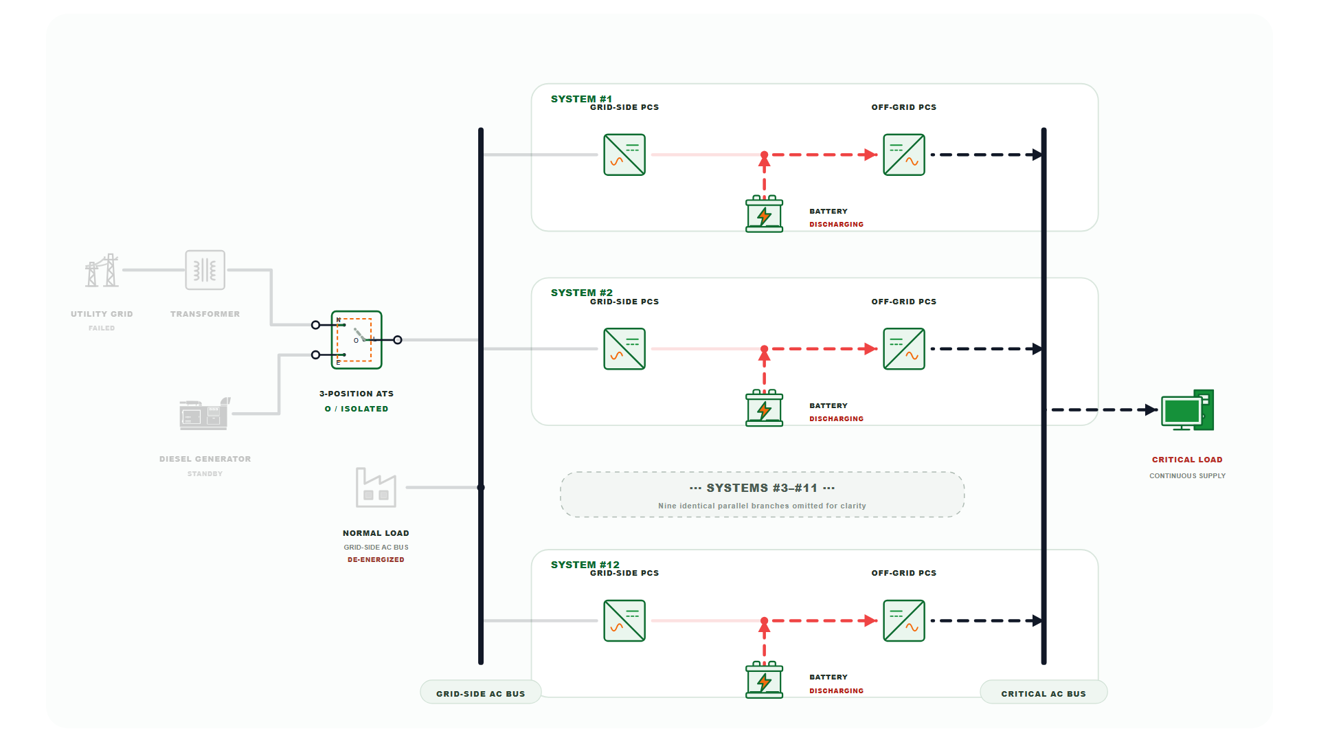
ATS moves to O. Batteries discharge through the off-grid PCS fleet to maintain the critical-load bus; normal load is de-energized.
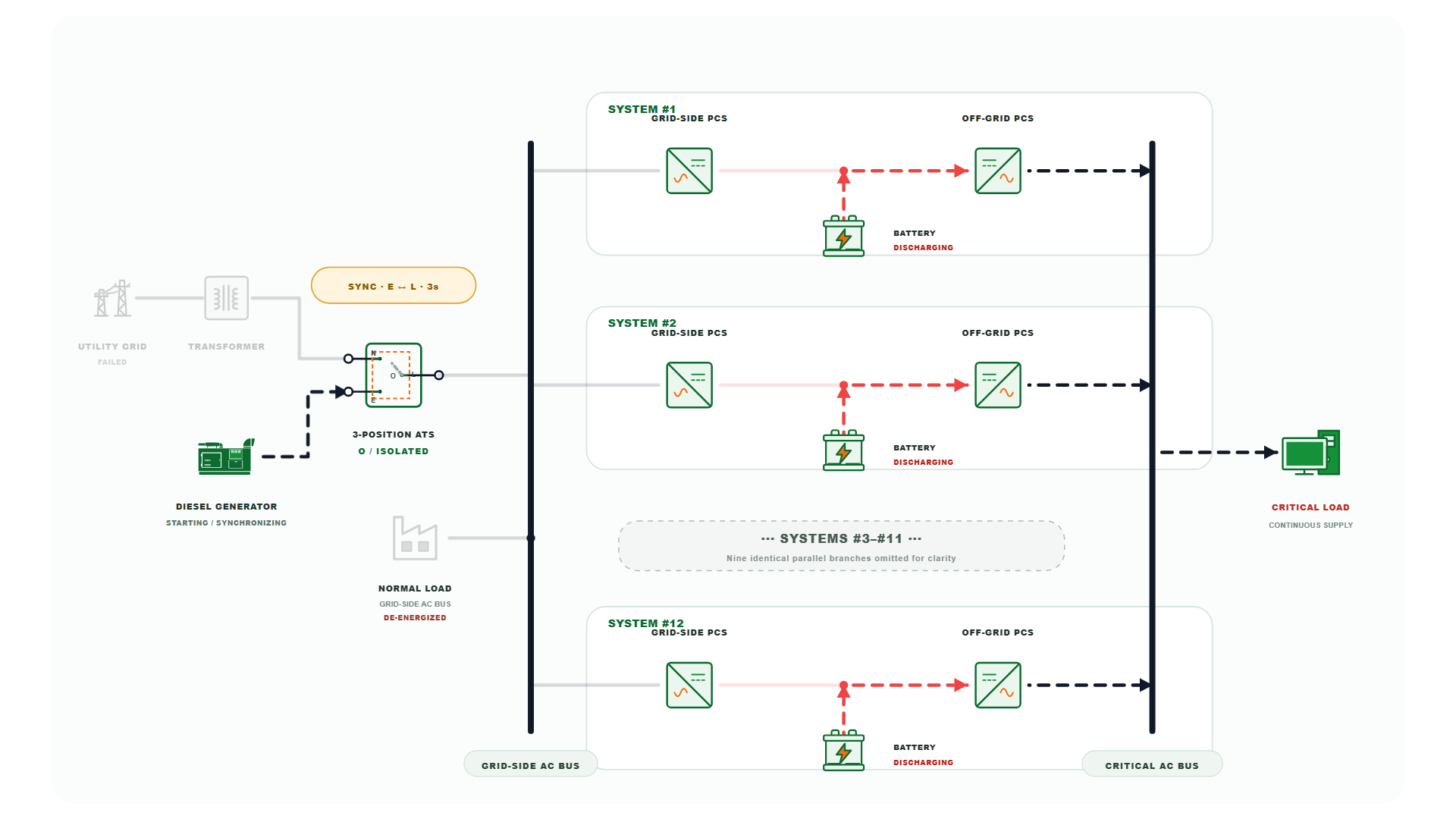
DG starts and establishes voltage. ATS remains at O during synchronization while the critical bus stays on battery / off-grid PCS supply.
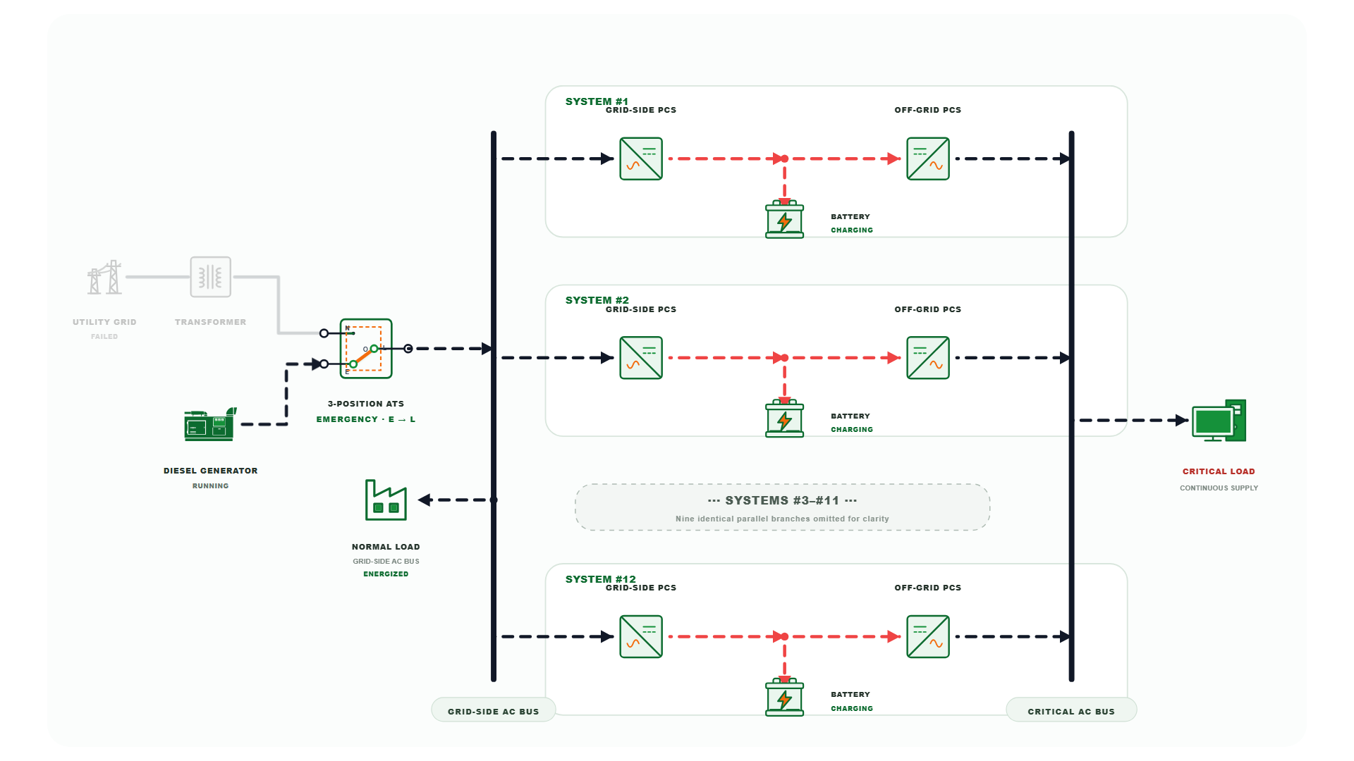
ATS transfers to Emergency. DG supplies the grid-side AC bus and normal load; grid-side PCS recharge the batteries.
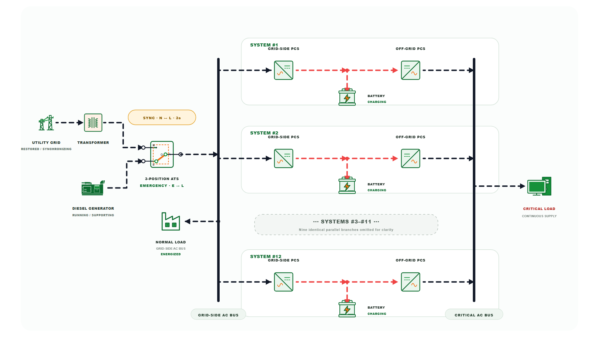
Utility returns while DG still supports the bus. The Normal source synchronizes before ATS transfers back to Normal and DG is unloaded.
Separate the charging role from the continuity role.
The architecture is valuable where a critical-load bus must remain supported while grid-side conditions change.
Grid-side PCS handles charging and grid interaction; dedicated off-grid PCS maintains the critical-load AC bus.
During a utility outage, Battery → DC node → Off-grid PCS remains the critical-load supply path.
A failed grid-side PCS stops charging, while its battery and off-grid PCS can remain available to the critical bus.
The battery bridges continuity; the generator restores the grid-side AC bus after start-up and synchronization.
Designed for sites where downtime matters.
The exact scope of the critical-load bus should be defined project by project according to power, duration, protection and compliance requirements.
Protect selected production and control loads.
- PLC / automation
- Process control
- Critical production lines
Support selected continuity-sensitive electrical loads.
- Control systems
- Auxiliary infrastructure
- Selected critical circuits
Maintain selected loads where interruption has high operational cost.
- Laboratory equipment
- Refrigeration
- Selected critical circuits
Combine battery continuity with long-duration generator support.
- Telecom
- Control centers
- Transport systems
Questions to answer before turning the concept into a project.
These answers describe the architecture shown on this page. Project-specific protection, cable sizing, earthing, transfer requirements and certification still require engineering confirmation.
No. This is a battery-energy-storage architecture designed to provide UPS-like continuity for selected critical loads while retaining a modular BESS structure. The exact project boundary and compliance requirements should be defined for the target application.
If you don’t have interval data, we work with monthly bills but the model has wider uncertainty bands. For larger projects (> 500 kW) we recommend installing an interval meter first.
The grid-side PCS is responsible for grid interaction and charging. The off-grid PCS is responsible for maintaining the critical-load AC bus. Separating these functions is the key architectural idea.
The ATS moves to the isolated O position. Batteries discharge through the off-grid PCS fleet to keep the critical bus supplied, while the normal load on the grid-side AC bus is de-energized until another source is admitted.
The critical loads continue on battery / off-grid PCS supply. The generator starts and establishes voltage, then synchronizes before the ATS transfers to the Emergency source.
The affected charging PCS stops charging. In the reference architecture, its battery and off-grid PCS remain available to the critical-load bus while the other grid-side PCS continue normal charging operation.
The battery’s SoC reserve for backup is configurable per site (typically 20-30% kept for emergency backup, 70-80% available for daily arbitrage).
Yes, depending on the required backup duration and battery sizing. The generator is used in this reference architecture to extend backup duration after a prolonged utility outage.
Discuss your critical-load architecture.
Share your critical-load power, required backup duration, utility configuration and generator information. The application team can then define the appropriate PCS, battery and ATS architecture