
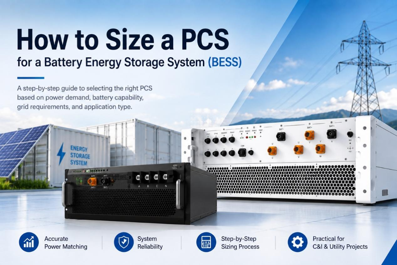
Choosing the right power conversion system (PCS) is critical to the performance, efficiency, and reliability of a battery energy storage system (BESS). An undersized PCS may limit power delivery, while an oversized unit can increase cost without adding value. This guide explains how to size a PCS based on power demand, battery capability, grid requirements, and application type, with practical considerations for C&I and utility-scale BESS projects.
BESS PCS Sizing Guide: What You’ll Learn
This guide explains how to determine the correct PCS rating for different battery energy storage applications. It covers the relationship between battery capacity, PCS power rating, and key system requirements.
It is intended for BESS engineers, project developers, electrical designers, and C&I energy users. After completing the sizing process, you will understand how to calculate PCS power requirements, evaluate system constraints, and avoid common selection mistakes.
What You Need Before Sizing a PCS for BESS
Before sizing a PCS, define the BESS application, review grid requirements, and prepare the required technical data. These inputs determine the PCS rating and system configuration.
Define Your BESS Application
The PCS rating depends on the BESS purpose. Peak shaving requires enough power to reduce demand during peak periods. Backup power requires sufficient output for critical loads. Solar-plus-storage requires the PCS to manage power flow between solar generation, battery storage, and the grid.
Understand Grid and Interconnection Requirements
The PCS must match site electrical conditions and grid requirements. Key factors include interconnection limits, power factor requirements, AC voltage level, and protection settings.
PCS Sizing Data, Tools, and Resources
The main resources required include:
- Load data: Utility bills or interval demand data.
- Battery and PCS datasheets: Power rating, voltage range, and operating limits.
- Single-line diagram or electrical drawings: Grid connection, transformer, and protection information.
- PCS sizing calculator or spreadsheet: PCS power calculation and system verification.
Step-by-Step Guide to BESS PCS Sizing
After defining the BESS application and collecting the required technical information, the next step is to calculate the appropriate PCS size. The sizing process should start from the required power output and then consider electrical constraints, battery capability, and system design requirements.
The following guide provides a step-by-step approach to selecting the right PCS rating for different BESS applications.
Step 1: Determine Required Active Power Output (kW)
Start by calculating how much AC power the BESS needs to deliver. The PCS active power rating should match the maximum power requirement of the application.
For peak shaving, use the target demand reduction. For backup power, use the critical load requirement. For solar-plus-storage, consider the required power flow between the battery, solar system, and grid.
The basic calculation is:
- Required PCS Power (kW) = Required Load Support or Peak Reduction Power
For example, a facility requiring 500 kW of peak demand reduction needs a PCS with at least 500 kW active power output.
Step 2: Convert kW to kVA and Match Battery Discharge Power
After determining the required kW output, convert it to PCS apparent power capacity.
The conversion depends on the power factor:
- kVA = kW ÷ Power Factor
For example, 500 kW at a power factor of 0.9 requires approximately 556 kVA PCS capacity.
The battery discharge capability must also match the PCS rating. A higher-rated PCS cannot increase output if the battery cannot provide sufficient power.
Step 3: Check Electrical, Grid, and Environmental Constraints
After calculating the required PCS size, verify that the selected PCS can operate within the site conditions.
The main checks include:
- AC voltage compatibility
- Transformer capacity
- Grid import/export limits
- Protection requirements
- Temperature and altitude derating
If the PCS output exceeds the site’s electrical limits, additional upgrades or power control strategies may be required.
Step 4: Select PCS Configuration and Apply Design Margin
The next step is selecting the appropriate PCS type based on project scale and installation requirements.
For C&I BESS projects, string PCS solutions are often preferred because they provide modular capacity and easier expansion.
For utility-scale BESS projects, central PCS solutions are commonly used because they support higher power ratings with fewer units.
A design margin can be added to account for future load changes, system losses, and operating conditions. However, excessive oversizing increases equipment cost without improving system performance.
Step 5: Verify Battery–PCS Compatibility and Finalize Selection
Before finalizing the PCS, confirm that the battery system and PCS can operate together.
The key compatibility checks include:
- Battery DC voltage range and PCS input voltage range
- Maximum charging and discharging power
- Communication between BMS and PCS
- Protection and safety functions
After completing these checks, select the PCS rating that meets the required power output, battery capability, and grid requirements.

Key PCS Considerations for C&I and Utility-Scale BESS
After completing basic PCS sizing, additional project-specific factors should be evaluated. These factors may not directly determine PCS power rating but can affect equipment selection and long-term operation.
Commercial & Industrial BESS
For C&I projects, additional considerations are often related to site conditions, operating patterns, and future system requirements. Since these systems are usually integrated into existing facilities, the PCS design should align with the facility’s electrical environment and installation limitations.
Load analysis should be based on interval demand data rather than only monthly electricity bills. Detailed demand profiles help identify actual operating patterns and support better decisions for energy management strategies.
The selection between string PCS and central PCS should consider available installation space and future expansion plans. The preferred configuration may vary depending on whether the project requires phased capacity expansion or a fixed system layout.
The PCS should also be compatible with the facility’s three-phase electrical system to ensure proper integration with existing infrastructure.
Utility-Scale BESS and Grid-Forming Systems
Utility-scale BESS projects require additional evaluation of grid functions and system coordination.
Grid-forming capability should be considered for applications such as island operation, weak-grid support, and renewable energy integration. Compared with grid-following PCS, grid-forming PCS can establish voltage and frequency references for additional grid support.
Large-scale projects also require coordination between PCS, transformers, and protection systems. Certification and interconnection requirements should be considered early to reduce project delays.
Further reading: How to Choose a PCS for a Microgrid
Common PCS Sizing Mistakes to Avoid
Even with a clear sizing process, some common mistakes can lead to incorrect PCS selection. These errors usually occur when the relationship between battery capacity, PCS power, and system operating requirements is misunderstood.
Mistake 1: Confusing Battery Capacity (kWh) with PCS Power (kW)
Battery capacity and PCS power represent different system characteristics. Battery capacity, measured in kilowatt-hours (kWh), defines how much energy the battery can store. PCS power, measured in kilowatts (kW), defines how much power the system can deliver at a specific time.
A larger battery capacity does not automatically require a larger PCS. For example, a 1,000 kWh battery can be paired with different PCS ratings depending on the required discharge duration and application needs.
The PCS should be selected based on the required power output, while the battery capacity should be selected based on the required operating duration.
Mistake 2: Sizing PCS Based on Peak Load Instead of Actual Duty Cycle
Another common mistake is selecting the PCS only according to the highest load value.
The maximum load does not always represent the actual BESS operating requirement. A facility may experience short-duration peaks that do not require continuous high-power discharge.
PCS sizing should consider the system duty cycle, including discharge frequency, operating duration, and expected daily usage pattern. This approach helps avoid unnecessary oversizing and improves project economics.
Mistake 3: Overlooking Derating from Temperature or Altitude
Environmental conditions can affect the available PCS output power. High ambient temperature and high installation altitude may reduce equipment performance because of thermal limitations and cooling requirements.
The PCS datasheet should be reviewed for operating temperature range, altitude limits, and applicable derating factors. If environmental conditions exceed standard operating conditions, additional design adjustments may be required.
Considering these factors during the sizing process helps ensure the PCS can deliver the expected power throughout the system operating life.
Choosing the Right PCS Power Rating for Your BESS
Selecting the right PCS power rating helps ensure that a BESS can meet application requirements while maintaining reliable operation. Enjoypowers provides PCS solutions for both commercial & industrial and utility-scale energy storage projects, with different power ranges and system features to support various deployment scenarios.
For C&I BESS applications, the 105/125kW PCS is designed for flexible energy storage systems that require advanced grid support and stable operation. Key advantages include: