
Project Background
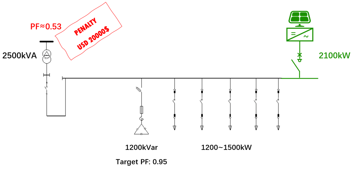
A machinery manufacturing facility operated the following electrical system:
- Transformer capacity: 2500 kVA
- Typical load power: approximately 1200–1500 kW
- Existing capacitor compensation: 1200 kVar
- Capacitor-bank target power factor: 0.95
Before installing photovoltaic generation, the facility’s monthly average power factor was generally above 0.95 and the electrical system operated normally.
The facility later installed approximately 2100 kW of photovoltaic generation.
After the PV system entered operation, an unexpected problem appeared.
The monthly grid-side power factor dropped significantly, reaching approximately 0.53 under the reported billing condition.
The facility subsequently faced an electricity penalty of approximately USD 20,000.
Why Did the Power Factor Fall?
The key was not simply the presence of the PV inverter.
The PV installation fundamentally changed the direction and magnitude of active-power flow at the grid connection point.
Before PV installation:
Grid supplied most of the facility’s active power.
After PV installation:
PV supplied a large part of the active power locally.
During periods of high PV generation, grid active-power import could become very low or even reverse.
However, the facility still required reactive power.
Therefore, the ratio between grid-side active and reactive power changed dramatically.
Existing Reactive-Power Controller Limitation
The existing capacitor-bank controller had been designed for a conventional one-directional electrical system.
Its measurement and control logic assumed that active power flowed from the grid toward the load.
When PV production exceeded part of the facility load, the power-flow condition changed.
Under those operating conditions, the existing controller could no longer regulate the capacitor bank correctly.
As a result, the original 1200 kVar capacitor compensation system was not being used effectively.
The grid therefore continued supplying substantial reactive power while active-power import had been greatly reduced.
This caused the grid-side power factor to fall.
Why Adding More Capacitors Was Not the Best First Step
The facility already had a large capacitor bank.
The problem was not simply insufficient installed capacitor capacity.
Instead, the main issue involved:
- Measurement
- Control logic
- Bidirectional power flow
- Dynamic reactive-power regulation
Adding more conventional capacitor capacity without solving the control problem could have created:
- Over-compensation
- Additional switching
- Potential leading power factor
- More complex system behavior
The solution therefore focused on integrating the existing capacitor system with active compensation.
Enjoypowers Solution
The project used a hybrid reactive-power compensation architecture.
1. Add Dynamic SVG Capacity
Two 100 kVar Enjoypowers SVG units were installed.
The SVGs provided fast and continuous reactive-current regulation.
2. Retain the Existing Capacitor Bank
Instead of discarding the existing 1200 kVar capacitor system, it remained part of the compensation architecture.
This allowed the existing equipment to continue providing bulk capacitive reactive power.
3. Coordinate Active and Passive Compensation
The SVG and capacitor system were coordinated so that:
- Capacitor stages supplied a large portion of reactive power
- SVGs provided dynamic fine adjustment
- Grid-side power factor could be regulated more accurately
This created a hybrid compensation system.
Result
After the two 100 kVar SVG units were installed and integrated with the existing capacitor system, the facility’s monthly average power factor recovered to above 0.95.
The project demonstrates that low power factor after PV installation is not always solved by increasing capacitor-bank capacity.
The first step should be to understand how the PV system has changed:
- Active-power direction
- Reactive-power demand
- Measurement points
- Compensation-controller behavior
Why This Problem Is Increasingly Relevant
Commercial and industrial sites are increasingly installing:
- Rooftop PV
- Energy storage
- Hybrid inverters
- EV charging
- Power-electronic production equipment
Electrical systems that were originally designed for one-directional utility power flow are now becoming bidirectional.
This creates new requirements for:
- CT placement
- Metering
- Reactive-power control
- Power-factor regulation
- Export conditions
- Harmonic management
Traditional compensation equipment may still be useful, but its control architecture needs to be reviewed.
Recommended Checks Before Adding Large C&I PV
Before connecting a large photovoltaic system to an existing industrial facility, check:
Existing Reactive-Power System
- Capacitor-bank capacity
- Controller type
- Controller measurement logic
- CT position
- Reactor configuration
Grid Connection
- Import/export requirements
- Utility PF requirements
- Metering point
- Transformer capacity
PV System
- PV inverter capacity
- Reactive-power capability
- External control capability
- Operating power factor
Site Loads
- Maximum and minimum active power
- Reactive-power demand
- Harmonic spectrum
- Major nonlinear loads
This analysis is especially important where PV capacity is close to or greater than the facility’s daytime load.
Engineering Principle
A successful C&I PV project should coordinate three systems:
PV generation
Facility loads
Reactive-power compensation
Treating these systems separately can result in unexpected behavior after commissioning.
For existing plants, field measurements during different PV and load conditions are the most reliable basis for designing the compensation strategy.
Need Help with a Similar Project?
If your facility experiences:
- Power-factor penalties after PV installation
- Incorrect capacitor switching
- Reverse power flow
- Harmonic amplification
- Reactive-power control problems
send the following information to the Enjoypowers engineering team:
- Single-line diagram
- Transformer capacity
- PV capacity
- Load profile
- Capacitor-bank information
- Utility PF requirement
- Power-quality measurement data
Email: sales@enjoypowers.com
Contact: https://enjoypowers.com/contact/