
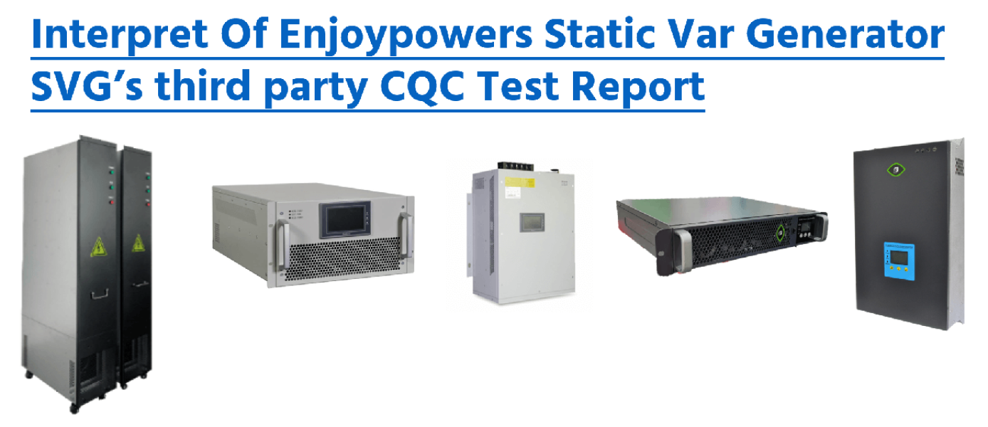
Introduction
Performance data is one of the most important references when evaluating a Static VAR Generator (SVG).
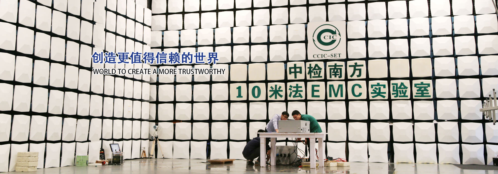
In 2020, the Enjoypowers SinE-100S44L SVG was tested by CCIC Southern Testing Co., Ltd. The test covered electrical safety, protection functions, reactive power performance, response characteristics, harmonic performance and electromagnetic compatibility.
This article summarizes the major information contained in that historical test report.
The results described below apply to the tested sample and test conditions stated in the report. For current product certification and specifications, always refer to the latest Enjoypowers documentation.
Test Report Information
Application number: V2019CQC020018-467031
Report number: C-02101-V202008674(XG1)
Product: Static VAR Generator
Model: SinE-100S44L
Testing organization: CCIC Southern Testing Co., Ltd.
Completion date: April 3, 2020
Test basis: DL/T 1216-2013, Technical Specification for Static Var Compensation Device for Distribution Network
How the Tested SVG Operates
The SVG measures load and system electrical quantities and determines the reactive-current component that requires compensation.
The converter then uses PWM-controlled power semiconductors to generate compensating reactive current.
The principle can be simplified as:
Load reactive current → measurement and calculation → converter control → opposite reactive current → reduced grid-side reactive current
Unlike mechanically switched or step-controlled capacitor systems, an SVG can continuously regulate its reactive output within its operating range.
This is particularly useful in applications where the load changes rapidly.
Main Test Categories
The third-party test program covered a broad range of items, including:
- Visual and structural inspection
- Protection class
- Clearance and creepage distance
- Insulation resistance
- Power-frequency withstand voltage
- Measurement accuracy
- Protection functions
- Temperature rise
- Continuous operating range
- Constant reactive-power control
- Reactive-power tracking
- Power-factor control
- Step response
- Loss assessment
- Harmonic performance
- Harmonic compensation
- Continuous operation
- Noise
- Electromagnetic compatibility
- Fast transient immunity
- Burst interference
- Electrostatic discharge immunity
The tested items applicable to the sample were recorded as qualified in the report.
Electrical Insulation Performance
Insulation Resistance
The reported insulation resistance was greater than 100 MΩ:
- Between phase conductors
- Between phase conductor and enclosure
Power-Frequency Withstand Voltage
The tested sample was subjected to specified withstand-voltage tests.
No discharge or equipment damage was reported under the stated test conditions.
These tests help verify the insulation integrity of the electrical equipment.
Protection Functions
The test report evaluated a number of protection functions, including:
- DC bus overvoltage
- DC bus undervoltage
- Drive-board fault
- Overtemperature
- AC overvoltage
- AC undervoltage
- Output overcurrent
- Cooling-system abnormality
The unit also included a power-on self-test function.
If an abnormal condition is detected, the controller can block normal operation and provide an alarm according to the defined protection strategy.
Temperature-Rise Test
Temperature rise is an important factor in long-term reliability.
During the test, key components such as:
- Soft-start resistors
- Inductors
- Fuses
- Transformers
- Relays
- Capacitors
- Control components
- Enclosure
- HMI
were monitored.
The reported temperature rises remained within the specified test limits under the stated conditions.
Dynamic Step Response
One of the main advantages of an SVG is its ability to respond dynamically to changes in reactive-power demand.
The report included several step-change tests, such as:
- 0 to +100 kVar
- +100 kVar to 0
- 0 to −100 kVar
- −100 kVar to 0
- +100 kVar to −100 kVar
- −100 kVar to +100 kVar
The reported response times varied according to the direction and magnitude of the step.
For example, the report recorded:
- 0 → +100 kVar: 2.2 ms
- +100 kVar → 0: 2.96 ms
- 0 → −100 kVar: 4.76 ms
- −100 kVar → 0: 1.84 ms
- +100 kVar → −100 kVar: 7.8 ms
- −100 kVar → +100 kVar: 3.88 ms
These figures are historical test values for this tested sample and should not automatically be applied to every current SVG model.
Operating Loss
At approximately rated reactive output, the report recorded active-power losses of approximately 2.4% under the tested operating conditions.
The test included both inductive and capacitive reactive-power output.
For current efficiency or loss specifications, refer to the latest product datasheet because hardware platforms and product generations may differ from the 2020 sample.
Power-Factor Control
The report also evaluated power-factor control.
The tested SVG changed its reactive output according to the target power-factor setting while the simulated load conditions were varied.
This type of control allows an SVG to dynamically compensate reactive power instead of relying only on discrete capacitor-bank switching.
Actual system-level performance still depends on:
- CT measurement position
- Load fluctuation
- System configuration
- Installed SVG capacity
- Control parameters
Output Harmonic Performance
The report measured the harmonic distortion of the SVG’s own output current during rated inductive and capacitive operation.
Reported THDi values were below approximately 3% for the measured phases under the stated test conditions.
This test helps determine whether the compensation equipment itself introduces excessive harmonic current.
Harmonic Compensation Test
The test setup also evaluated harmonic-current compensation.
Before compensation, the measured phase harmonic currents were approximately 99 A.
After compensation, they were approximately 18 A under the specific laboratory test conditions.
This corresponds to a remaining harmonic-current RMS level of roughly 18% of the original measured value in the test setup.
This is a laboratory result under defined conditions, not a universal field-performance guarantee.
Actual harmonic-compensation performance depends strongly on:
- Harmonic order
- Harmonic current magnitude
- AHF/SVG capacity
- Grid impedance
- Background voltage distortion
- CT accuracy
- System topology
Noise Test
Under the test conditions, measured noise around the equipment was approximately:
- Front: 54.6 dB
- Rear: 50.1 dB
- Left: 49.8 dB
- Right: 52.1 dB
Noise performance varies with load, fan operation, installation environment and product model.
Electromagnetic Compatibility Tests
The report included electromagnetic compatibility and immunity tests such as:
- Radiated electromagnetic-field immunity
- Burst interference
- Electrostatic discharge
During the documented tests, the equipment was evaluated for continued operation, temporary performance changes and recovery according to the applicable acceptance criteria.
What Does This Test Report Tell Us?
The report is useful because it evaluates more than reactive-power capacity alone.
It covers four important aspects of an SVG:
1. Electrical Safety
Insulation and withstand-voltage tests verify fundamental electrical integrity.
2. Dynamic Performance
Step-response testing provides information about how quickly the device reacts to changing reactive-power demand.
3. Compensation Performance
Power-factor and reactive-current tests demonstrate the control capability of the converter.
4. Reliability and EMC
Temperature, protection and electromagnetic-immunity tests help evaluate operation under abnormal or disturbed conditions.
Important Note on Historical Test Reports
This test was completed in 2020 on model SinE-100S44L.
Enjoypowers products have continued to evolve since then.
Therefore:
Do not use this historical article as the sole certification or specification reference for a current project.
For procurement, tendering or engineering design, always use the current:
- Datasheet
- User manual
- Certificate
- Test report
- Product selection guide
provided for the exact model being supplied.
For current documentation, contact: