
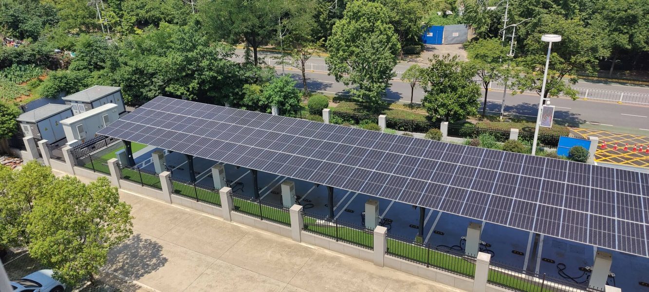
Introduction
Distributed photovoltaic systems can significantly reduce grid energy consumption for commercial and industrial users.
However, connecting a large PV system changes the electrical conditions at the point of common coupling.
If the existing electrical system was designed before PV was installed, the interaction between:
- PV inverters
- Existing loads
- Transformers
- Capacitor banks
- Harmonic sources
- Reactive-power controllers
may create new power-quality problems.
Typical symptoms include:
- Low power factor
- Unexpected capacitor-bank behavior
- Harmonic amplification
- Main breaker tripping
- Capacitor fuse operation
- Voltage distortion
- Three-phase imbalance
- Utility penalties
The PV system itself is not necessarily the only cause. In many projects, the underlying problem is the interaction between the new PV generation and an existing compensation system.
How a Grid-Connected PV System Changes Power Flow
A PV inverter converts DC energy from solar modules into AC power.
When PV output increases, the active power imported from the utility decreases.
For a facility:
Grid active power = Load active power − PV active power
However, the facility’s reactive-power demand may not decrease by the same proportion.
This creates an important power-factor issue.
Why Power Factor Can Fall After PV Installation

Power factor is related to active power and apparent power.
Consider a factory that originally imports:
- High active power from the grid
- A certain amount of reactive power
After installing PV, the PV system supplies part of the active power locally.
Grid active power therefore decreases.
But if the facility’s reactive-power demand remains similar, reactive power becomes larger relative to grid active power.
Consequently, the measured grid-side power factor can fall.
This effect can become especially significant around periods of:
- High PV generation
- Low facility load
- Export to the grid
Existing Capacitor Controllers May Also Be Affected
Many older reactive-power controllers were designed primarily for one-directional power flow.
After distributed generation is added, grid-side power may approach zero or reverse direction.
Depending on the controller design and measurement method, this can interfere with:
- Reactive-power calculation
- Capacitor-stage switching
- Power-factor regulation
The result may be insufficient compensation or incorrect switching.
For this reason, the entire measurement and control architecture should be reviewed whenever significant PV generation is added to an existing industrial electrical system.
Harmonic Issues
PV inverters are power electronic converters.
Modern equipment is designed to meet applicable grid harmonic requirements, but the overall site harmonic condition depends on more than the PV inverter alone.
A factory may already contain harmonic-producing loads such as:
- Variable frequency drives
- UPS systems
- Rectifiers
- High-frequency heating equipment
- Welding machines
- Switched-mode power supplies
When PV generation, capacitor banks and these nonlinear loads interact with the system impedance, harmonic levels may change.
Harmonic Resonance
One particular risk is resonance.
Capacitors together with the inductance of transformers and cables can create resonant frequencies.
If a significant system harmonic is close to a resonant frequency, harmonic current or voltage can be amplified.
Possible symptoms include:
- Capacitor overheating
- Fuse failure
- Excessive capacitor current
- Voltage distortion
- Breaker overheating
- Nuisance tripping
Therefore, simply increasing capacitor capacity after PV installation may make the situation worse if harmonic conditions have not been evaluated.
Three-Phase Unbalance
Three-phase unbalance can also occur in PV applications.
Possible causes include:
- Uneven single-phase inverter allocation
- Different PV array orientations
- Partial shading
- Uneven generation
- Existing unbalanced loads
For large three-phase commercial PV systems, the PV itself is often balanced, but the overall facility should still be evaluated at the point of connection.
Common Reactive-Power Control Approaches
Several approaches are used in commercial PV systems.
1. PV Inverter Reactive-Power Control
Some PV inverters can provide reactive power according to:
- Fixed power factor
- Q setpoint
- Volt-VAR function
- External controller commands
This can be useful when properly coordinated.
However, available reactive-power capability is related to inverter apparent-power capacity and operating conditions.
2. Existing Capacitor Banks
Existing capacitor banks can continue to provide low-cost reactive power.
However, the controller must correctly handle the new bidirectional power-flow conditions.
3. Static VAR Generator
An SVG can dynamically regulate capacitive or inductive reactive current.
This is useful when the reactive-power requirement changes rapidly or when precise grid-side PF regulation is required.
4. Active Harmonic Filter
Where excessive harmonic current exists, an AHF can be added specifically for harmonic compensation.
5. Hybrid Compensation
TSC/capacitor stages can provide bulk reactive power while SVG/AHF equipment provides dynamic fine compensation and harmonic mitigation.
Case Study: Metal Processing Plant
A metal processing factory had the following electrical system:
- Transformer: 1000 kVA
- Electrical load: approximately 500–600 kW
- Around 30% of the load consisted of high-frequency heating equipment
- Existing capacitor bank: 300 kVar
- Historical monthly average power factor: above 0.90
Before the PV system was installed, the electrical system operated normally.
Problems After PV Connection
After PV generation was added, the plant experienced:
- Power factor falling to around 0.8
- Repeated capacitor fuse operation
- Capacitor damage
- Main breaker tripping
Site measurements showed that the problem involved the interaction between the existing capacitor compensation system and harmonic-producing industrial equipment.
The original capacitor current was significantly higher than its rated value.
Measurements also showed amplification of the 11th- and 13th-order harmonic components.
The recorded THDi increased from approximately 18% to 43% under the problematic operating condition.
This demonstrated that the project was not simply a “low power factor” problem.
It was a combined:
reactive power + harmonics + resonance problem.
Implemented Solution
The final solution addressed the two problems separately.
Reactive-Power Compensation
A 200 kVar SVG was installed together with an appropriately configured capacitor/reactor system to provide hybrid reactive-power compensation.
Harmonic Compensation
A 200 A active harmonic filter was installed for the high-frequency heating equipment.
This architecture allowed:
- Capacitors to provide bulk reactive power
- SVG to dynamically regulate reactive power
- AHF to mitigate harmonic current
Result
After implementation, the plant’s monthly average power factor increased to above 0.95.
The previously reported breaker-tripping problem was also eliminated during the observed operating period.
The case illustrates an important principle:
Power-quality problems after PV installation should be diagnosed from measurements rather than assuming that additional capacitors alone will solve the problem.
Recommended Diagnostic Process for PV Projects
When low power factor or harmonic problems appear after PV connection, review the system in this order:
Step 1 — Record Operating Conditions
Measure conditions during:
- No PV
- Low PV
- High PV
- Low load
- High load
- Export operation where applicable
Step 2 — Measure Power Quality
Record:
- Active power
- Reactive power
- Power factor
- THDi
- THDu
- Harmonic spectrum
- Three-phase current
- Three-phase voltage
Step 3 — Review Existing Compensation Equipment
Check:
- Capacitor capacity
- Capacitor current
- Reactor ratio
- Controller measurement method
- CT position and direction
Step 4 — Determine the Actual Problem
Separate:
- Reactive-power problem
- Harmonic problem
- Resonance problem
- Three-phase unbalance
- Control problem
Step 5 — Select the Appropriate Technology
Use:
- Capacitors/TSC for bulk reactive power
- SVG for dynamic reactive-power compensation
- AHF for harmonic compensation
- Hybrid architecture where appropriate
Conclusion
Distributed PV changes the way active power flows through an industrial electrical system.
That change can expose weaknesses in older capacitor-control systems or alter harmonic and resonance conditions.
For this reason, power-quality design should be considered as part of large commercial and industrial PV projects rather than only after a problem occurs.
For project analysis, provide:
- Single-line diagram
- Transformer data
- PV capacity
- Load profile
- Existing capacitor-bank information
- Power-quality measurements
to the Enjoypowers engineering team.
Email: sales@enjoypowers.com
https://enjoypowers.com/contact/