
1 Background and Application Requirements
Commercial and Industrial (C&I) energy storage systems are widely used in grid-tied applications such as peak shaving, energy optimization, and grid frequency regulation. When a grid outage occurs, the PCS (Power Conversion System) from Enjoypowers can operate in Off-grid Mode to provide power to loads. However, the challenge lies in providing an uninterruptible backup power supply for critical loads.
1.1 From “Energy Storage” to “Backup Power”
1.1.1 Why PCS Cannot Achieve Seamless Switching Alone?
Most C&I energy storage PCS units operate in Grid-tied Mode (PQ Mode) during normal operation. In this state, the PCS functions essentially as a “Grid-Following” Current Source. It relies on the voltage and frequency provided by the grid as a reference, tracking the grid phase via a Phase Locked Loop (PLL). The Energy Management System (EMS) controls the charging and discharging strategy, and the PCS is responsible only for the active or reactive current output.
Once a grid fault occurs (such as a short circuit or disconnection), the voltage reference disappears instantly, and the PCS PLL unlocks immediately. To prevent the PCS from feeding power back into a faulty grid (which endangers maintenance personnel), all grid-connection standards (such as GB/T 34120) mandate that the PCS must disconnect and stop output immediately upon detecting a loss of grid voltage. This mechanism is known as Anti-Islanding Protection.
1.1.2 The Challenge of Off-grid Mode: From “Following” to “Forming”
If the energy storage system is required to continue supplying power after an outage, the PCS must switch to Off-grid Mode (VF Mode). In this state, the PCS transforms from a “Current Source” to a “Grid-Forming” Voltage Source, independently establishing stable voltage and frequency for the load. Since many loads are single-phase, the PCS is required to provide 3P4W output with 100% three-phase unbalanced load capability.
1.1.3 How to Switch from Grid-tied to Off-grid Mode?
In traditional energy storage systems, the transition from “Grid-tied Operation” to “Grid-tied Shutdown” and then to “Off-grid Restart” typically relies on manual operation or slow mechanical switching. The process is as follows:
- Grid failure occurs, PCS shuts down, load loses power.
- Manual confirmation of fault; opening of grid-side circuit breaker (to prevent reverse power flow).
- Manually modifying the PCS operating mode to Off-grid Mode.
- Sending the startup command; PCS performs Soft Start to build up voltage.
- This entire process typically takes 1 to 15 minutes. This duration implies that critical loads cannot avoid a power outage.
1.2 Core Value of the Static Transfer Switch (STS)
To enable the energy storage system to provide uninterruptible backup power for critical loads, an intelligent device capable of responding to grid status within milliseconds must be introduced: the Static Transfer Switch (STS).
2 Technical Principle and Topology of STS
2.1 Core Components and Working Principle of STS
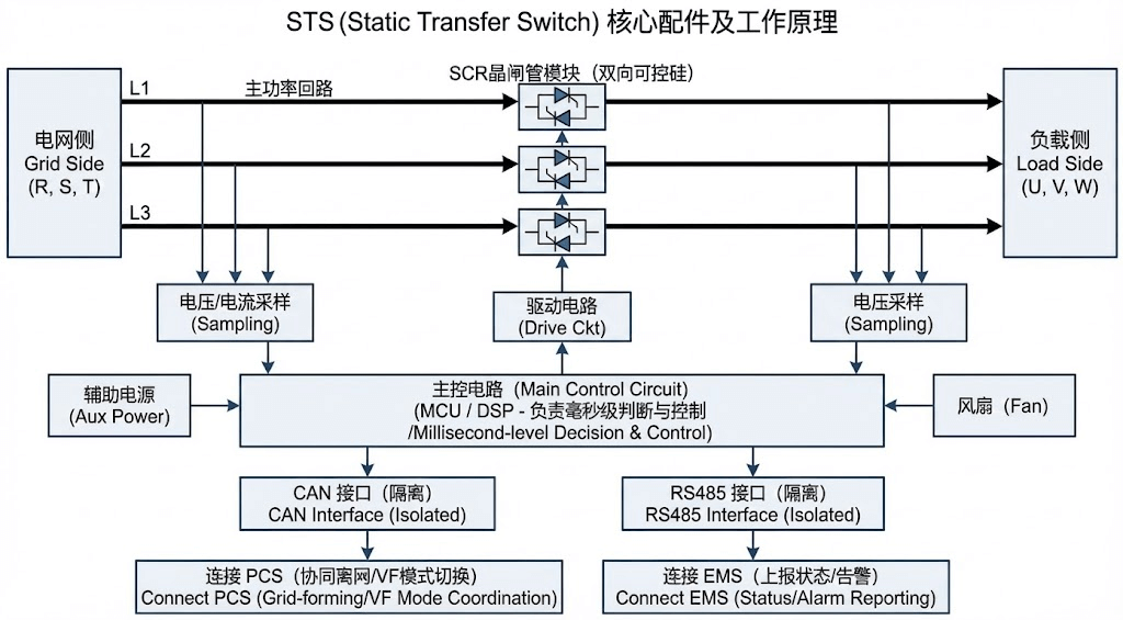
Image 1: STS Core Components and Working Principle Diagram
As shown in the figure, the STS is primarily composed of Bi-directional Thyristor (SCR) modules connected in series within the main circuit between the grid side and the load side.
- Sampling & Control: The main control circuit (MCU/DSP) performs high-frequency sampling of voltage and current on both sides, calculating amplitude, frequency, phase, phase sequence, and Total Harmonic Distortion (THD) in real-time.
- Drive & Execution: The SCR zero-crossing switching is precisely controlled via an optocoupler-isolated drive circuit, achieving millisecond-level action.
- Communication & Coordination: The STS provides two isolated communication interfaces: A CAN interface for millisecond-level data interaction with the PCS (e.g., Phase Dispatch, coordinated mode switching), and an RS485 interface for status monitoring by the EMS.
- Power Assurance: An uninterruptible 24Vdc auxiliary power supply must be configured to ensure the STS controller can still perform logic judgment and drive actions under extreme Total Power Loss scenarios.
2.2 Typical Topology and Capacity Sizing of STS
2.2.1 Typical Topology Structure
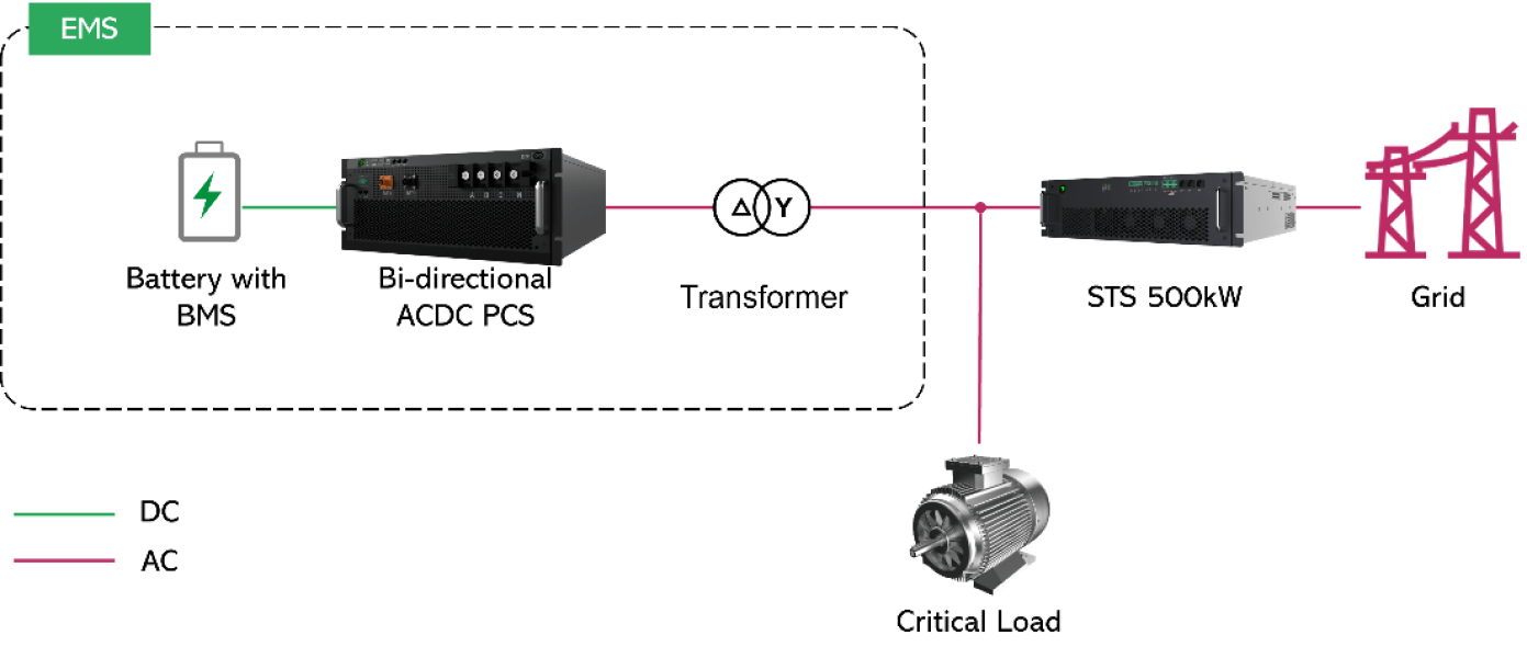
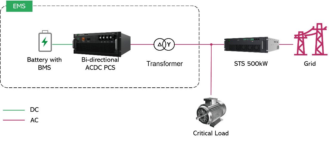
The standard connection involves placing critical loads between the STS and the PCS, while non-critical loads are connected between the STS and the grid, achieving graded protection.
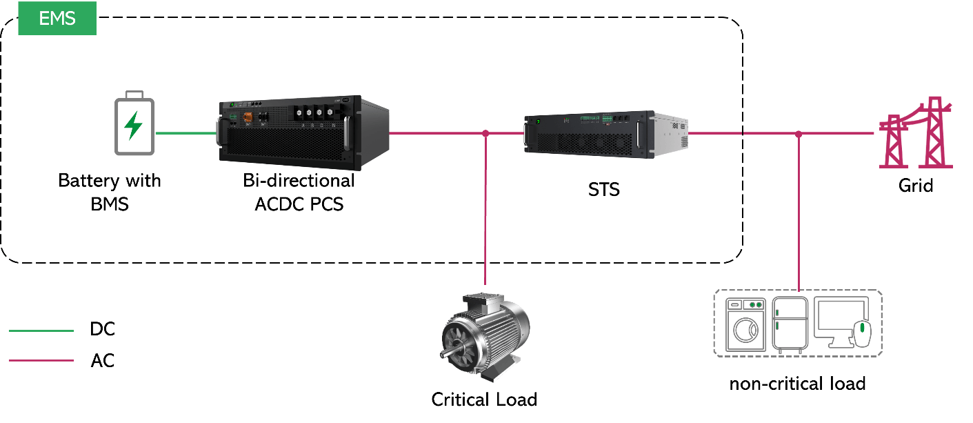
Image 2: System Topology Diagram including EMS, Battery, PCS, Transformer, STS, Grid, and Loads
2.2.2 STS Capacity Sizing Principles
The STS serves as the master switch at the Point of Common Coupling (PCC). Its capacity selection should follow the principle of “sizing up, not down”:
- Standard Principle: STS rated capacity ≥ Maximum Critical Load Power + Maximum PCS Charging Power.
- Controlled Principle: In scenarios where the grid is solely a backup power source, and the EMS can ensure the STS does not run into overload via PCS charge/discharge control strategies, the STS capacity may be reduced to match the PCS charging power.
2.3 Analysis of Key Switching Timing
2.3.1 Switching from Grid-tied to Off-grid State (Due to Grid Fault)
- Fault Isolation: The STS detects a grid fault (Under/Over Voltage, Under/Over Frequency, Voltage Sag, Distortion) and rapidly blocks the SCR drive signal within <2ms, physically severing the grid connection.
- Mode Command: The STS sends a high-priority “Go Off-grid” command to the PCS via the CAN bus.
- Voltage Build-up: Upon receiving the command, the PCS immediately switches from PQ (Current Source) Mode to VF (Voltage Source) Mode and establishes output voltage smoothly via Soft Start, preventing inrush current impacts on transformers or loads.
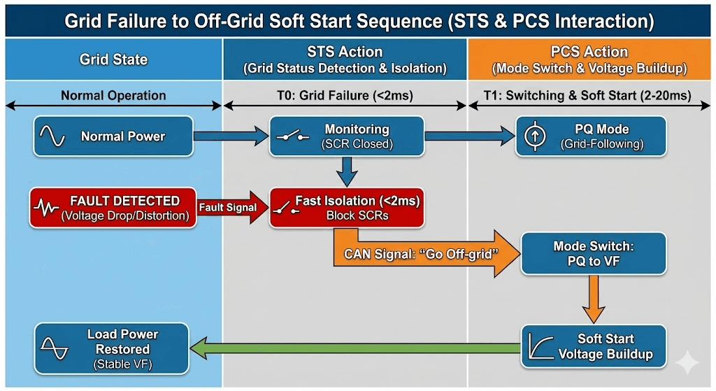
Image 3: Grid Failure to Off-Grid Soft Start Sequence Diagram
2.3.2 Switching from Off-grid to Grid-tied State (Due to Grid Recovery)
- Recovery Judgment: The STS confirms that grid voltage, frequency, and phase have recovered to normal ranges and remain stable.
- Phase Dispatch: The STS locks the grid phase and packs the real-time phase angle to send to the PCS via the CAN bus.
- Active Tracking: The PCS adjusts its output frequency so that its phase approximates the grid phase.
- Seamless Closure: When the PCS detects that the phase difference is less than the preset threshold (e.g., 5°), it issues a close command: The STS conducts the SCRs while the PCS simultaneously switches back to PQ Mode. The synchronization of this action is critical to ensuring a smooth grid connection without surge currents.
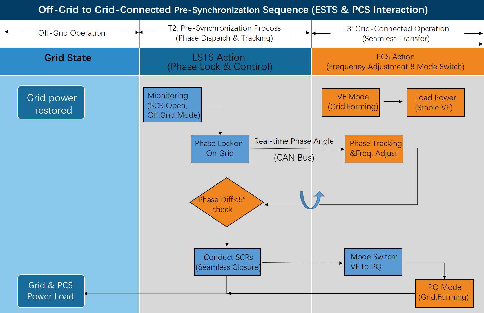
Image 4: Off-Grid to Grid-Connected Pre-Synchronization Sequence Diagram
3 STS Engineering Guide: Hardware Configuration and Wiring
3.1 Core Specifications for Physical Wiring
To ensure nanosecond-level synchronization accuracy and system safety, the following specifications must be strictly observed:
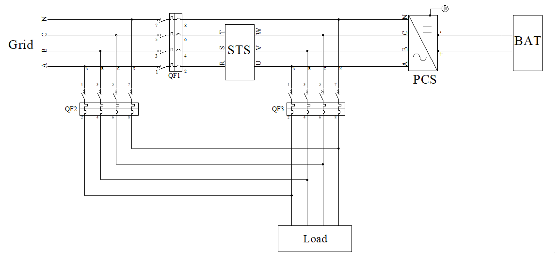
- N-wire (Neutral) Handling: In TN-S systems, it is recommended that the N-wire does not pass through the STS (i.e., N-wire direct connection). This ensures the N-G potential remains constant during switching, preventing neutral point drift that could damage single-phase loads.
- Maintenance Bypass: A maintenance bypass switch with a Mechanical Interlock must be configured to ensure loads remain powered during STS maintenance.
- CAN Communication Cable Requirements:
- Cable Type: Twisted shielded pair cables must be used, with anti-interference magnetic rings added at both ends.
- Length Limitation: The CAN bus length between the STS and PCS is STRICTLY PROHIBITED from exceeding 15 meters (10 meters or less is recommended). Excessive length causes attenuation or delay of high-frequency synchronization signals, affecting phase-lock accuracy.
- Topology Requirement: A “Daisy Chain” (Linear) topology must be used. Star connections are strictly prohibited.
3.2 Hardware DIP Switch Configuration for CAN Communication
The STS and PCS achieve millisecond-level data interaction via the CAN bus. For stable communication, correct settings for CAN addresses and termination resistors are required.
Address Allocation Rules:
- PCS Address: Numbered consecutively starting from 1 (1, 2, …, N), supporting a maximum of 4 parallel units.
- STS Address: Fixed setting of 5.
Termination Resistor Configuration Rules:
The CAN bus must use a “Daisy Chain” topology. Enable the 120Ω termination resistor ONLY on the devices at the two furthest physical ends of the bus. The resistor DIP switches on intermediate devices must be in the OFF state.
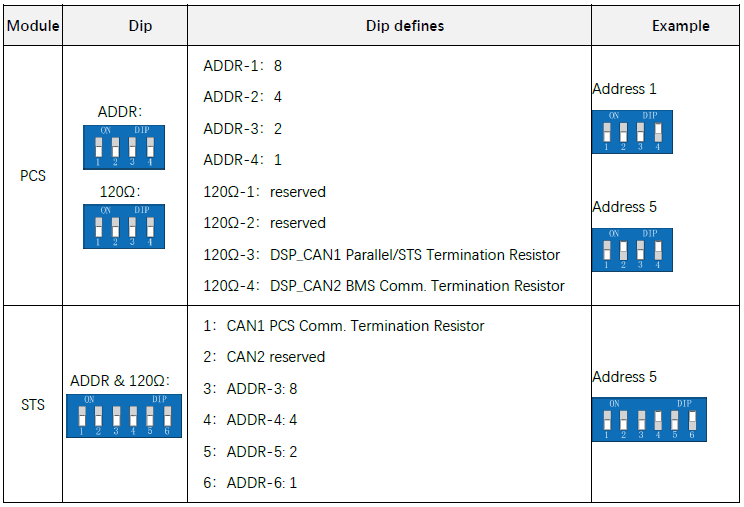
Table 1: DIP Switch Definitions for PCS and STS
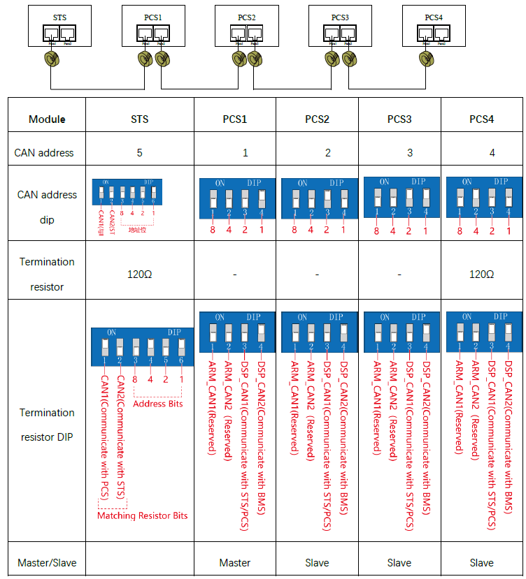
l Typical Configuration Example (1 STS + 4 PCSs)
In a system comprising 1 STS and 4 PCS units in parallel, PCS1 is designated as the Master in Off-grid Mode. The STS and all PCS units are on the same CAN bus using a linear topology. The physical link ends are the STS and PCS4.
- Physical Link: STS <-> PCS1 <-> PCS2 <-> PCS3 <-> PCS4
- STS: Address set to 5, Termination Resistor ON.
- PCS1~3: Addresses set to 1~3, Termination Resistor OFF.
- PCS4: Address set to 4, Termination Resistor ON.
4 STS Engineering Guide: Software Parameter Settings
4.1 Critical Parameters for PCS (via EMS/Upper Computer)
Before system power-up and commissioning, configure the following PCS parameters:
4.1.1 PCS Basic Electrical Parameters:
- Voltage/Frequency Level (0x5001/0x5002): Must strictly match the grid voltage/frequency connected to the STS (e.g., 400V/50Hz).
NOTE: If a transformer exists between the PCS and STS, enter the voltage of the PCS side of the transformer, not the grid side.
- Wiring Mode (0x501C):
- Default setting is 0-3P4W (Three-phase Four-wire).
- If a Delta/Wye Isolation Transformer exists between the PCS and STS, and the PCS side has no Neutral line, this must be set to 1-3P3W (Three-phase Three-wire). Otherwise, a voltage sampling fault will occur because the Delta winding side has no physical neutral point, preventing phase voltage sampling.
- Transformer Phase Angle (0x1669): If a Delta/Wye transformer exists, taking the common DYn11 winding as an example, the PCS transformer angle difference needs to be set to 300 (representing a 30° lag) to compensate for the 30° phase lead generated by the transformer.
4.1.2 PCS Operating Mode and Logic:
- Operating Mode (0x5066): Set to Off-grid Mode. This ensures the storage system has the capability to establish a voltage source, which is the software basis for working with the STS.
- Master/Slave Setting (0x5068): For multi-unit parallel operation, designate only one PCS as “Master (1)”; set the rest as “Slave (0)”.
4.1.3 PCS Communication Target:
- STS Host Address (0x1012): Enter the actual CAN address set on the STS (e.g., 5).
- Communication Enable (0x506C): Set to 1-Enable to activate the handshake function with the STS.
4.2 Critical Parameter Settings for STS
4.2.1 STS Communication Target:
- PCS Host Address (0x1012): Enter the CAN address of the PCS Master (usually 1) to ensure the STS knows where to send synchronization commands.
4.2.2 STS Special Scenario Configuration (WARNING: DO NOT MISCONFIGURE):
- Diesel Gen Mode (0x506E):
- When connected to the Grid: Set to 0-Grid Mode.
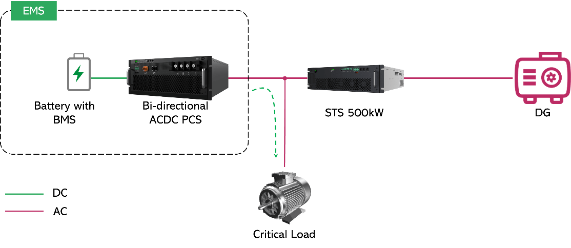
- When connected to a Diesel Generator: Set to 1-Diesel Gen Mode. This mode widens the frequency protection range to accommodate generator fluctuations. Misconfiguration may cause STS false triggering or refusal to act.
- Transformer Mode (0x506F):
When a Delta-Wye (Δ/Y) isolation transformer exists between the PCS and load, set to 1-Enable.
Enabling this mode allows the STS to use a conduction angle Soft Start strategy during Reverse Charging of the Transformer by the Grid (PCS not running) or Black Start with Transformer to suppress inrush current. During Synchronous Grid Connection, the STS will perform a rapid zero-crossing closure to ensure waveform integrity.
5 Auxiliary Power and EMS Monitoring System
Necessity: In a “Total Power Loss Scenario” (Grid loss AND PCS has not yet established voltage), the STS controller must remain online to execute logic judgments.
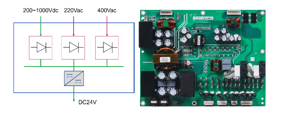
Solution: Configure an APS module supporting Triple Redundant Inputs: HVDC (Battery) + AC (Grid) + AC (PCS Output), outputting a stable 24Vdc.
5.1 Key Accessory: APS Power Supply
To ensure reliable 24Vdc power input for the STS through multi-source redundancy, we offer the APS accessory. This module features triple inputs, capable of drawing power from the Grid side, the PCS AC side, and the Battery DC side respectively. It outputs a stable 24Vdc to guarantee the normal operation and communication of the STS.
Critically, this ensures that the STS controller remains powered to execute control logic and maintain CAN communication even during a total system power loss scenario (i.e., when the Grid is lost and the PCS has not yet established voltage).
5.2 EMS Monitoring Solution
In a complete energy storage system, the EMS can communicate with the STS via RS485 for monitoring. Alternatively, the EMS can obtain STS working status via the PCS Modbus register 0x2212. For retrofitting STS into existing systems, seamless switching can be achieved by configuring the PCS and STS settings, even without modifying the EMS.
6 Standard Operating Procedures for PCS and STS
6.1 Grid-tied Startup Procedure
- Power Up & Wait: Grid is connected; STS detection is normal.
- Status: POWER light solid ON, FAULT light OFF, RUN light flashing (Standby).
- Link Conduction: PCS sends “Conduct” command to STS (via CAN).
- Status: STS RUN light solid ON, SCR conducts, main circuit closes.
Grid-tied Operation: EMS sends “Start” command to PCS.
Action: PCS begins inverting; system enters grid-tied operation.
6.2 Off-grid/Black Start Procedure
- Status Confirmation: System is not connected to the grid.
- Status: STS POWER light OFF, FAULT light ON (Grid Phase Loss/Abnormal).
- Logic: Conduction conditions are not met; PCS will NOT send a conduction command to the STS.
- Black Start: EMS sends “Start” command to PCS.
- Action: PCS outputs voltage in VF Mode to support the load. STS remains open to achieve physical isolation.
7 Troubleshooting Common Issues
7.1 Synchronization/Grid-connection Failure
- Symptom: After grid recovery, the system remains in “Pre-synchronization” state and does not close.
- Root Cause Analysis:
- Communication Delay: Single CAN cable is too long, causing phase data packet lag and poor phase-lock accuracy.
- Phase Deviation: Δ/Y transformer exists in the system, but “Transformer Mode” is not enabled.
- Source Jitter: Excessive fluctuation in Grid or Diesel Generator prevents PLL from locking.
7.2 Power Drop during Switching
- Symptom: Relays trip or equipment reboots during switching.
- Cause: PCS voltage build-up time is too long (>20ms); or STS protection thresholds are set too wide (action taken only after deep voltage drop).
7.3 Abnormal EMS Monitoring Data
- Troubleshooting: Check if the mapping address of PCS register 0x2212 in Solution B is shifted; check if CAN communication heartbeats are normal.
7.4 Short Circuit Damage due to Incorrect Phase Sequence
WARNING: The physical phase sequence (A/B/C) of the STS Input Side (Grid) and PCS Output Side must be strictly consistent. Software cannot correct physical phase sequence wiring errors. If phases are reversed (e.g., A-C swapped), a Phase-to-Phase Short Circuit will occur at the moment of grid connection, causing severe equipment damage. It is MANDATORY to use a phase sequence meter to verify both sides before commissioning.
7.5 Redundant Configuration Requirements for Auxiliary Power
- STRICTLY PROHIBITED: Do not rely solely on AC Grid power for the STS. In a “Total Power Loss Scenario” where the grid fails and the PCS has not yet established off-grid voltage, if the STS loses control power, it cannot maintain communication or logic judgment, resulting in switching failure.
- MANDATORY REQUIREMENT: The APS (24Vdc) must be connected, and it must be ensured that the APS accepts Battery Side DC (HVDC) as the ultimate backup power source.
8 Maintenance and Environment
8.1 Routine Inspection Items
- Real-time monitoring of inverter input/output voltage, current, and running status is required. Designated personnel should perform spot checks:
- Listen: No abnormal sounds from the converter.
- Smell: No abnormal odors inside the converter.
- Read: Internal temperature readings are within the normal range.
8.2 Periodic Maintenance
- Check converter appearance for damage or rust.
- Verify internal temperature is normal using thermal imaging/thermometer.
- Ensure surrounding ventilation, ambient temperature, humidity, and dust levels meet requirements.
- Check cables for insulation aging or damage; replace or insulate if necessary.
- Check terminal bolts for signs of aging or scorching; tighten by hand/tool to ensure secure connection.
8.3 Application Environment Specifications
In high salt mist or high dust environments, special installation processes are required; standard deployment is not suitable. Pay attention to cleaning and anti-corrosion measures. Maintenance intervals should be shortened in harsh environmental conditions.
Cooling: The STS module uses forced air cooling (front intake, rear exhaust). When installed in an integrated cabinet, the cabinet air inlet must align with the module. The module inlet distance from the cabinet inlet must be ≥110mm. An exhaust duct must be added to the module outlet to direct hot air directly to the cabinet outlet, preventing hot air recirculation within the cabinet.