
The PCS is the bridge between your battery bank and the grid — and its topology directly influences system efficiency, harmonic performance, and long-term operating cost. Two-level and three-level are the two most common PCS topologies in today’s energy storage market. This guide explains how each one works, compares them across eight practical dimensions, and offers a framework to help you evaluate which topology better fits your project.
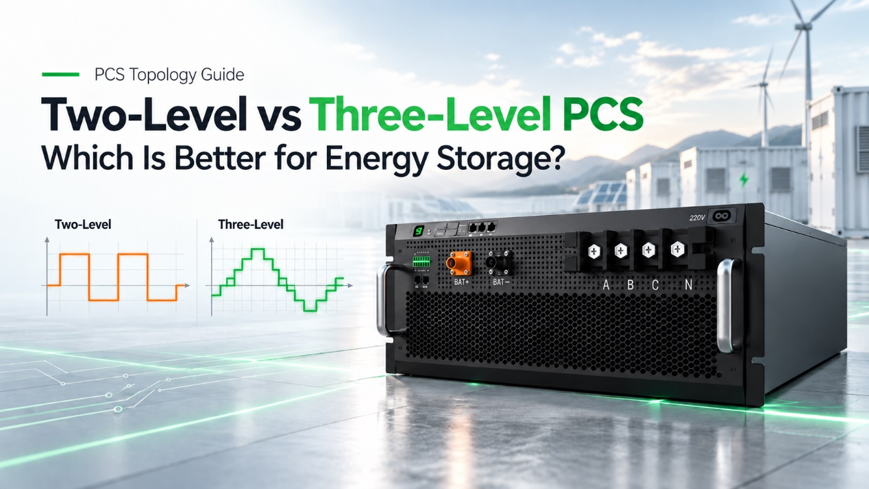
What Is a Two-Level PCS?
A two-level PCS is an inverter design that alternates its output voltage between exactly two distinct states: the positive and negative Direct Current (DC) bus voltage. It represents the standard, established approach to electrical power conversion.
Key Functions
The key function of this system is to convert DC electricity from storage batteries into Alternating Current (AC) for grid usage, and vice versa. It achieves this bidirectional flow using a straightforward switching sequence.
Advantages
- Structural Simplicity: The straightforward circuit design uses fewer internal components, minimizing potential points of failure.
- Lower Initial Cost: Less complex hardware and standard control software generally reduce the upfront purchase price.
- Accessible Maintenance: Standardized internal layouts make field repairs and troubleshooting easier for site technicians.
Limitations
- Higher Voltage Stress: Internal electronic components must handle the full DC bus voltage during every switching cycle.
- Increased Harmonics: Sharp voltage transitions generate higher Electromagnetic Interference (EMI) and demand larger external output filters.
- Thermal Constraints: Higher switching losses produce more internal heat, requiring bulkier cooling systems.
What Is a Three-Level PCS?
A three-level PCS is an advanced inverter architecture that switches its output voltage among three defined states: positive, neutral (zero voltage), and negative. This intermediate zero-voltage step creates a more refined electrical output.
Key Functions
Similar to the two-level model, its key function remains the bidirectional conversion of AC and DC power. However, it manages this process by distributing the electrical load across a larger number of internal semiconductor components.
Advantages
- Superior Waveform Quality: The intermediate voltage step significantly reduces harmonic distortion and electrical noise.
- Higher System Efficiency: Lower voltage jumps reduce switching losses, resulting in higher overall energy conversion rates.
- Reduced Component Stress: The electrical load is distributed across multiple semiconductors, which extends hardware lifespan.
- Compact Footprint: Lower localized heat generation and smaller magnetic filters allow for higher cabinet power density.
Limitations
- Increased Complexity: The internal architecture requires additional semiconductor switches and highly sophisticated control algorithms.
- Higher Upfront Cost: The necessity for advanced neutral-point balancing software and extra hardware typically raises the initial unit price.
Two-Level vs Three-Level PCS: Side-by-Side Comparison
Evaluating these topologies requires a structured technical comparison. Before looking at the side-by-side data, you need to understand what each criterion measures and how it directly impacts your project.
- Circuit Architecture Complexity: This refers to the total number of internal semiconductor switches and their physical layout. It dictates your field maintenance strategy.
- Device Voltage Stress: This measures the maximum electrical load placed on individual internal components during operation. It impacts hardware longevity.
- Electromagnetic Interference: This represents the unwanted electrical noise generated by rapid voltage transitions. It determines site compatibility.
- Output Filter Requirements: This indicates the physical size and capacity of the external magnetic components needed to smooth the output waveform. It influences your physical footprint and budget.
- Control Software Complexity: This describes the sophistication of the mathematical algorithms required to manage power switching. It shapes the commissioning process.
- Thermal Management: This encompasses the internal heat generated by switching losses and the cooling mechanisms required to dissipate it. It drives auxiliary power consumption.
- System-Level Cost: This includes the initial unit purchase price plus the cost of all associated operational hardware like cooling and filters. It reveals the true financial return of your project.
- Power Scalability: This defines the system’s ability to operate at higher base voltages and expand total capacity by connecting multiple units. It determines your future-proofing capabilities.
Here is how the two-level and three-level architectures compare side-by-side across each dimension:
| Evaluation Criteria | Two-Level Architecture | Three-Level Architecture |
| Circuit Architecture Complexity | Uses fewer internal components. | Requires additional semiconductors. |
| Device Voltage Stress | Components handle the full direct current voltage. | Voltage is distributed across components. |
| Electromagnetic Interference | Generates noticeable electrical noise. | Produces smoother voltage transitions. |
| Output Filter Requirements | Demands bulky magnetic components. | Operates with compact filters. |
| Control Software Complexity | Uses standard modulation techniques. | Employs advanced neutral-point balancing. |
| Thermal Management | Demands heavy-duty cooling infrastructure. | Supports compact heat dissipation designs. |
| System-Level Cost | Cheaper unit price, costlier auxiliary gear. | Costlier unit price, cheaper auxiliary gear. |
| Power Scalability | Limited to standard commercial voltage levels. | Designed for utility-scale high-voltage expansions. |
Analysis and Insights: How to Choose the Right PCS Topology
Understanding the technical differences is only the first step; the next is applying them to your project’s specific goals. Here are the key insights to help you make the most cost-effective and reliable choice:
Architecture Simplicity vs Performance Trade-Off
Balancing internal complexity and energy efficiency plays a major role in your long-term project success. Two-level systems feature simpler internal layouts, which can make them quite suitable if your site relies on basic maintenance teams.
Conversely, three-level systems generally deliver higher power conversion efficiency. This characteristic often makes them preferable for commercial operations that prioritize long-term energy yields over initial hardware simplicity.
Waveform Quality Drives Hidden Cost Savings
The quality of the electrical output typically influences your overall expenditure on auxiliary equipment. Two-level systems produce sharper voltage transitions, which frequently require installing heavier magnetic filters to meet local grid codes.
Three-level systems tend to generate smoother electrical outputs more naturally. Consequently, this topology often allows you to select smaller filters, potentially reducing hidden installation costs and saving valuable cabinet space.
Thermal Design Determines Power Density Ceiling
Internal heat generation largely shapes how much power you can fit into a specific physical footprint. Two-level systems tend to concentrate switching losses, which typically calls for a more robust active cooling infrastructure to maintain safe temperatures.
Meanwhile, three-level systems distribute the electrical load to generate less localized heat. This thermal advantage can help hardware engineers design more compact cabinets for projects facing strict space constraints.
Unit Cost vs System Cost: Look at the Right Number
Evaluating the complete integration cost usually provides a clearer financial picture than looking solely at the standalone inverter price. A two-level system typically presents a lower upfront purchase price, which can fit well for projects with strict immediate capital limits.
However, a three-level system may ultimately prove more economical for comprehensive deployments. The higher initial unit cost is often offset by potential savings on cooling systems, filter sizing, and long-term operating efficiency.
Scalability Dictates the High-Power Default
Your planned operating voltages and future expansion needs frequently guide the final topology choice. Two-level systems generally perform well for standard commercial deployments operating at lower voltages with fixed, smaller capacities.
For modern, high-capacity systems, the three-level architecture is usually the more practical selection. It helps manage higher component voltage limits effectively and supports smoother capacity scaling as your site energy demands grow.
Recommended reading: How to Size a PCS for a Battery Energy Storage System
Common Applications for Two-Level and Three-Level Systems
Matching the right topology to practical operational conditions ensures the best balance of cost, performance, and reliability. Because each architecture possesses distinct electrical profiles, different site environments naturally favor one over the other.
Where Two-Level Systems Typically Excel
Due to their straightforward design, two-level systems provide dependable performance in scenarios where initial affordability and easy maintenance outweigh the demand for maximum electrical efficiency. You will frequently find them in:
- Small-to-medium commercial and industrial energy storage
- Rooftop solar-plus-storage for retail and office buildings
- Remote or off-grid power systems and small microgrids
- Budget-driven projects where upfront cost is the top priority
Where Three-Level Systems Typically Excel
Conversely, three-level systems serve as the optimal solution when project specifications demand higher power density, strict grid compliance, and lower harmonic distortion. They are the standard choice for:
- Large-scale grid-connected energy storage projects
- High-voltage 1500V battery system architectures
- Renewable energy integration with wind, solar, and storage hybrid plants
- Applications requiring premium power quality and grid-forming capability
Enjoypowers 105/125 kW PCS: Three-Level Performance Built for C&I Energy Storage
At Enjoypowers, we engineered our 105/125 kW PCS to prove why three-level topology fits commercial energy storage. By utilizing this advanced architecture, we solve practical field integration challenges rather than just hitting specification targets.
Here is how our design leverages three-level performance for your projects:
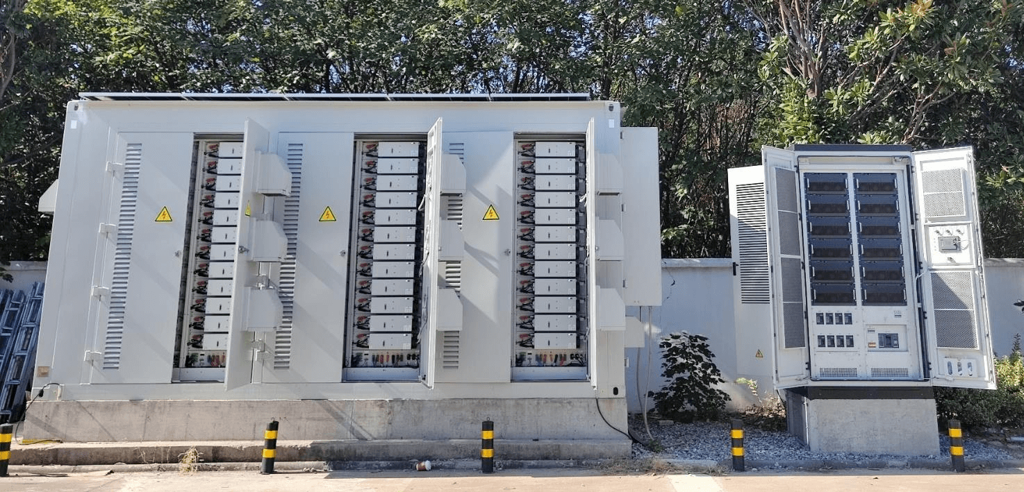
- Harsh Grid Tolerance: The smoother three-level output, combined with virtual impedance, stabilizes against severe grid THDu up to 30% while keeping output THDi strictly under 3%.
- Grid-Forming VSG Control: Precise switching enables robust Virtual Synchronous Generator control. This supports seamless on/off-grid transfers in under 20 milliseconds and allows stable multi-unit paralleling without extra communication wiring.
- 100% Independent Phase Control: The system commands each phase independently to support 100% unbalanced loads at full rated power. This eliminates the common “lowest phase wins” derating issue under zero-export rules.
- Industrial Reliability: Because three-level systems distribute heat effectively, we designed a highly compact IP20 module that operates reliably from -30 °C to +55 °C within protected commercial cabinets.
Empower Your Storage Strategy with the Right PCS
Selecting the ideal PCS topology fundamentally defines your project’s long-term profitability. While two-level units offer simplicity, three-level architectures unlock superior efficiency and compact footprints. At Enjoypowers, our 105/125 kW PCS harnesses this three-level technology to deliver utility-grade reliability and modular scalability for your commercial deployments.
Ready to optimize your next energy storage project? Contact Enjoypowers today to explore our advanced PCS solutions.
FAQs
Q1: Can a three-level PCS work for smaller C&I projects, or is it only for utility-scale?
Three-level PCS is no longer limited to utility-scale. Compact modules like the Enjoypowers 105/125 kW PCS bring three-level waveform quality and efficiency to C&I-scale projects in a modular form factor.
Q2: What if my project needs to scale up later — do I have to replace the PCS?
Not necessarily. Choose a PCS that supports communication-free parallel expansion. The Enjoypowers 105/125 kW PCS supports up to 12-unit comms-less parallel, scaling from 125 kW to over 1.25 MW without additional communication infrastructure.
Q3: How do I ensure my PCS meets grid codes across different countries?
Select a PCS with pre-certified multi-standard compliance and built-in grid-forming capability. The Enjoypowers 105/125 kW PCS ships with CE and G99 certifications, supports EN 50549 European grid compliance, plus native VSG grid-forming support — reducing compliance risk and speeding up interconnection.